
Wiring & Hardware
Wiring & hardware
ECU pinout links and the established wiring principles for CAN, analogue/NTC inputs, lambda interfaces and low-side relay outputs.
ECU pin-outs
CAN accessories
Add-on-module wiring uses +12 V, ground, CAN L and CAN H. A DTM example is pin 1 +12 V, pin 2 ground, pin 3 CAN L and pin 4 CAN H, with 500 kbit/s used by the accessory described there. Do not assume that baud rate for every ECU network or accessory.
Sensor inputs
Temperature sensor inputs
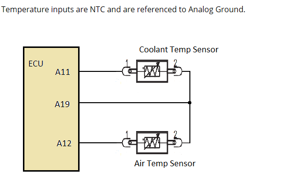
Temperature inputs use NTC sensors referenced to Analog Ground. The example below shows coolant and air temperature sensors connected between their respective ECU inputs and the common Analog Ground.
Auxiliary switched inputs
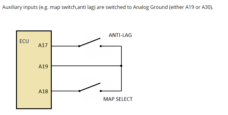
Auxiliary inputs such as Anti-Lag and Map Select are activated by switching the input to Analog Ground. Use the ECU-specific pin-out to identify the correct input and Analog Ground pins.
0–5 V linear analogue inputs
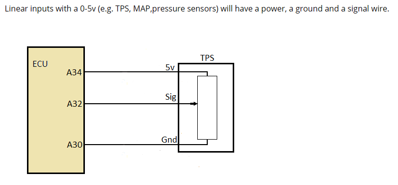
Linear 0–5 V sensors such as TPS, MAP and pressure sensors normally have a 5 V supply, Analog Ground and signal connection. Use the ECU-specific pin-out for the correct terminals and configure the sensor scaling in SXTune.
Outputs and relay wiring
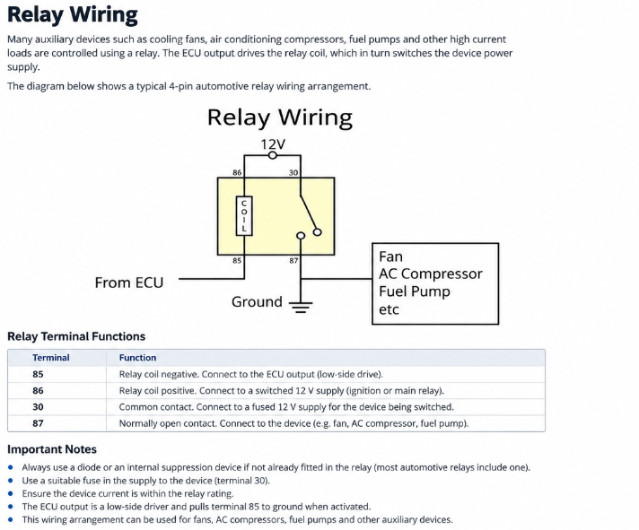
Delta relay outputs are low-side drivers: the ECU switches the negative side of the relay coil. The relay provides the higher-current switched supply required by devices such as cooling fans, air-conditioning compressors and fuel pumps.
Cooling and auxiliary outputs
Cooling fans and other auxiliary devices are controlled through configured ECU outputs. Configure the physical output first, then set the operating thresholds and hysteresis for the function it controls.
Cooling fans
Independent fan on/off coolant-temperature thresholds are provided. Use separated on/off values to prevent rapid relay cycling. ECU relay outputs switch the ground side of the relay, so the vehicle wiring must provide the relay 12 V feeds correctly.
Other temperature-driven functions
Supported functions include hot-soak pump control, ECU stay-alive after key-off, chargecooler pump control and idle offsets when cooling fans or air conditioning add engine load.