
Calibration & Control
On-board diagnostics (OBD)
SCS Delta ECUs have a OBD1 monitoring system on all relevant sensors and actuators.
It performs a continuous monitoring for the following sensors and actuators out of the table below:
List and purpose of all components monitored by the OBD system:
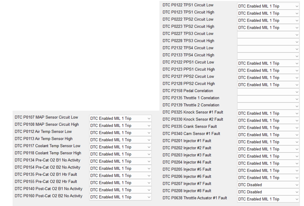
Image: List and purpose of all components monitored by the OBD system:
Electrical diagnosis of all sensors and activators against short and open circuit.
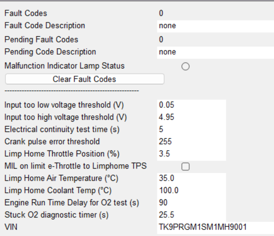
Image: General detection criteria of the OBD1 system as calibrated in the
The general working principle of the electrical monitoring system is such that the ecu checks the feedback voltage on the signal pin or over it pull up or pull down input stage against a set of thresholds.
If the signal voltage is lower than the input too low threshold for a bounce time longer than the electrical continuity test time in seconds, it will set the open circuit P code.
If the signal voltage is higher than the input too high threshold for a bounce time longer than the electrical continuity test time in seconds, it will set the short circuit P code.
For the air temperature sensor the replacement value is calibrated to 35°C in case of a detected DTC, both open loop or short circuit.
For the coolant temperature sensor the replacement value is calibrated to 100°C.
All OBD communication goes through the ISO 15765-4 (CAN) protocol following the normal SAE standards naming for all Detected Trouble Codes (DTC`s).
On the O2 sensors both upstream and downstream the working principle of the monitoring system is more advanced than for the other inputs.
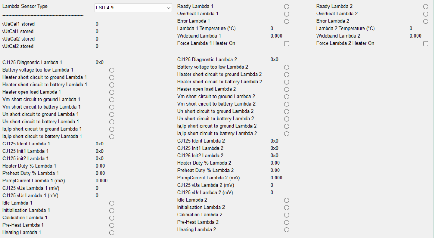
Image: CJ125 LSU control chip diagnostic output
The upstream wideband lambda sensors are controlled by the Bosch CJ125 chip oboard of the ECUs PCB. This chip performs a set of functional diagnostics on the wideband sensor and will set its own DTC whenever necessary. Each one of these DTCs will automatically stop the closed loop lambda control CLC and also directly light the Malfunction Indication Light MIL.
The downstream lambda sensors which are of the binary switching type, have another type of monitoring which checks the level of heater current over a certain time period. Detecting a current outside of the set thresholds would lead to the P0135 or P0155 DTC, lighting the MIL straight away as well as stopping the CLC feedback path for the downstream Post cat controller.
There is also a second sensor activity monitor which checks if the sensor value is not stuck over a calibrateable time period. In the , this time is set to 25s, meaning that the signal must be stuck for more than this time before the DTC is set.
Some of these diagnostic parameters are not calibrateable, they are defined in the firmware of the ecu. When set the P0140 or P0160 DTC will be activated, lighting the MIL straight away as well as stopping the CLC feedback path for the downstream Post cat controller.
Due to the safety relevance the monitoring on the Egas throttles is much more extensive. See the Electronic chapter of this description document for the full details on these monitors.
For crankshaft trigger-wheel monitoring, the ECU compares the number of teeth counted between missing-tooth gaps with the configured expected pattern. If the deviation exceeds the calibrated tolerance, a crank-sensor DTC such as P0335 can be set.
For the camshaft triggerwheel, the basic methodology is the same but calibrated specifically to the lower number of teeth on it. It will set the P0340 if necessary. This diagnostic is off course running for each of the 4 cam triggerwheels on the engine.
On the knock sensors, the monitor checks for stuck signal. A working and well connected knock sensor will always detect some noise during the engine operation and therefore the signal value can never be flat for a longer time.
I the signal is detected to be flat for longer than the calibrated debouce time for the electrical diagnosis, it will set the DTC.