
ECU Technical Reference
Delta 800 ECU technical reference
Hardware identification and connector pin-out.
ECU
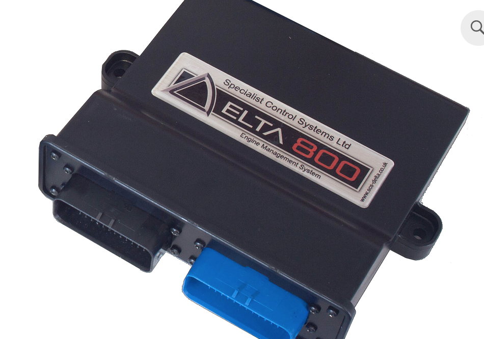
Pin-out
- Connector A: AMPSeal 776164-1
- Connector B: AMPSeal 776163-4
- CAN Connector: Female DB9
Connector A
| Pin | Name | Description | Notes |
|---|---|---|---|
| 1 | Battery | Direct Battery Supply (15A fuse) | Direct Battery Power 6-15V |
| 2 | Ignition | Ignition Switched Supply (10A fuse) | Ignition Key Input |
| 3 | Power Ground 1 | Power Ground | Power Ground 1 |
| 4 | Low Side Output 1 | 3A Open Collector | Injector 1 Output |
| 5 | Low Side Output 2 | 3A Open Collector | Injector 2 Output |
| 6 | Low Side Output 3 | 3A Open Collector | Injector 3 Output |
| 7 | Low Side Output 4 | 3A Open Collector | Injector 4 Output |
| 8 | Crank/Cam Ground | Digital Ground | Crank/Cam Sensor Ground |
| 9 | Crank Input | VR/Hall - Software Selectable | Crank Sensor Input |
| 10 | Cam Input 1 | VR/Hall - Software Selectable | Cam Sensor 1 Input |
| 11 | NTC Input 1 | 3.16K pull-up to VREF | Coolant Temperature Input |
| 12 | NTC Input 2 | 3.16K pull-up to VREF | Air Temperature Input |
| 13 | Ignition 1 | TTL/Power Ignition Output | Software Configurable Output |
| 14 | Ignition 2 | TTL/Power Ignition Output | Software Configurable Output |
| 15 | Ignition 3 | TTL/Power Ignition Output | Software Configurable Output |
| 16 | Ignition 4 | TTL/Power Ignition Output | Software Configurable Output |
| 17 | Analog Input 1 | 47k pull-up to VREF | Linear 1 Input |
| 18 | Cam Input 2 | VR/Hall - Software Selectable | Cam Sensor 2 Input |
| 19 | Analog Ground 1 | Analog Ground | Analog Ground |
| 20 | Lambda 1 Input | Weak bias to 450mV | Lambda Sensor 2 Input |
| 21 | CAN 1H | 120 Ohm Terminated | To PC comms DB9 |
| 22 | CAN 1L | To PC comms DB9 | |
| 23 | Low Side Output 5 | 3A Open Collector | Auxiliary 1 / Injector 5 Output |
| 24 | Low Side Output 7 | 3A Open Collector w/ recirc diode | Main Relay/PWM1 |
| 25 | Low Side Output 8 | 3A Open Collector w/ recirc diode | Fuel Pump Relay/PWM2 |
| 26 | Low Side Output 9 | 3A Open Collector w/ recirc diode | PWM3 Output |
| 27 | Low Side Output 10 | 3A Open Collector w/ recirc diode | PWM4 Output |
| 28 | Low Side Output 11 | 3A Open Collector with pull-up to VBATT via diode | Tachometer Output |
| 29 | Low Side Output 6 | 3A Open Collector | Auxiliary 2 / Injector 6 Output |
| 30 | Analog Ground 2 | Analog Ground | Analog Sensors Ground |
| 31 | NTC Input 3 | 3.16K pull-up to VREF | NTC1 Input |
| 32 | Analog Input 2 | 47k pull-up to VREF | Throttle Position Sensor Input |
| 33 | Analog Input 3 | 47k pull-up to VREF | Manifold Pressure Sensor Input |
| 34 | VREF | 500mA 5V supply to sensors | 5V Reference Sensor Supply |
| 35 | Power Ground 2 | Power Ground | Power Ground 2 |
Connector B
| Pin | Name | Description | Notes |
|---|---|---|---|
| B1 | H Bridge 1 M+ | 5A H-Bridge | Throttle Motor 1 + |
| B2 | H Bridge 1 M- | 5A H-Bridge | Throttle Motor 1 - |
| B3 | H Bridge 2 M+ | 5A H-Bridge | Throttle Motor 2 + |
| B4 | H Bridge 2 M- | 5A H-Bridge | Throttle Motor 2 - |
| B5 | Bipolar Output 1 | 3A Hi Side/Lo Side Drive | PWM5 Output |
| B6 | Bipolar Output 2 | 3A Hi Side/Lo Side Drive | PWM6 Output |
| B7 | Bipolar Output 3 | 3A Hi Side/Lo Side Drive | PWM7 Output |
| B8 | Bipolar Output 4 | 3A Hi Side/Lo Side Drive | PWM8 Output |
| B9 | Low Side Output 12 | 3A Open Collector | Injector 7 Output |
| B10 | Low Side Output 13 | 3A Open Collector | Injector 8 Output |
| B11 | Cam Input 3 | VR/Hall - Software Selectable | Cam Sensor 3 Input |
| B12 | Cam Input 4 | VR/Hall - Software Selectable | Cam Sensor 4 Input |
| B13 | Ignition 5 | TTL/Power | Software Configurable Output |
| B14 | Ignition 6 | TTL/Power | Software Configurable Output |
| B15 | Ignition 7 | TTL/Power | Short circuit protection for Power |
| B16 | Ignition 8 | TTL/Power | Short circuit protection for Power |
| B17 | Hall Input 1 | Hall Effect Input | Wheel Speed LR |
| B18 | Hall Input 2 | Hall Effect Input | Wheel Speed RR |
| B19 | Hall Input 3 | Hall Effect Input | Wheel Speed LF |
| B20 | Hall Input 4 | Hall Effect Input | Wheel Speed RF |
| B21 | Knock 1 + | Knock 1 Signal Input | |
| B22 | Knock 2 + | Knock 2 Signal Input | |
| B23 | Knock Ground | Digital Ground | |
| B24 | Lambda 2 Input | Weak bias to 450mV | Lambda 2 |
| B25 | Analog Input 4 | 47k pull-up to VREF | TPS2 |
| B26 | Analog Input 5 | 47k pull-up to VREF | PPS1 |
| B27 | Analog Input 6 | 47k pull-up to VREF | PPS2 |
| B28 | NTC Input 4 | 3.16k pull-up to VREF | NTC2 Input |
| B29 | NTC Input 5 | 3.16k pull-up to VREF | NTC3 Input |
| B30 | Analog Input 7 | 47k pull-up to VREF | Linear 5 Input |
| B31 | Analog Input 8 | 47k pull-up to VREF | Linear 6 Input |
| B32 | Analog Input 9 | 47k pull-up to VREF | Linear 7 Input |
| B33 | Analog Input 10 | 47k pull-up to VREF | Linear 8 Input |
| B34 | CAN 2L | CAN 2 Low | 120 Ohm Terminated |
| B35 | CAN 2H | CAN 2 High | |
| PC Comms DB9 Female Connector | |||
| Pin | Name | ||
| 1 | Ground | ||
| 6 | CAN High | ||
| 7 | CAN Low | ||
| 8 | Battery Voltage | ||
| DTM Connector | |||
| 1 | Battery Voltage | ||
| 2 | Ground | ||
| 3 | CAN High | ||
| 4 | CAN Low |