Calibration & Control
Ignition Calculations
Understand how the ECU calculates ignition timing from the base spark map, dwell and the applied timing corrections.
Base spark map
The base spark map provides the starting ignition timing over engine speed and load before the ECU applies the relevant corrections.
Ignition timing calculation
The spark advance/ ignition timing calculation starts from the base spark map:
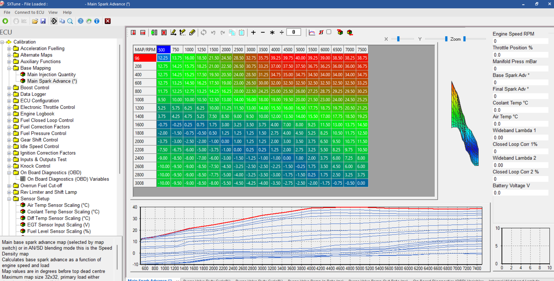
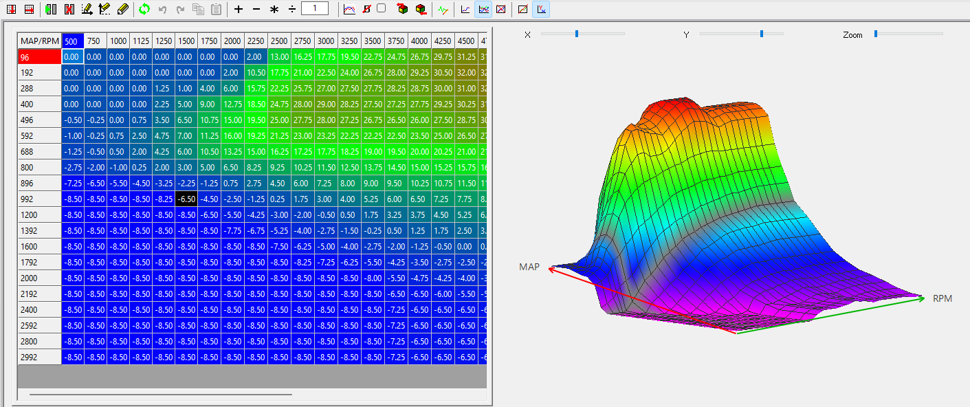
Image: the base spark table as calibrated in the
The base spark map goes over speed and load. In this example since we are running a speed density volumetric efficiency based set up on the , the load input is the intake manifold pressure. The breakpoints need to be set in such a way that all points of significant change in behaviour are covered correctly.
The optimal spark advance timing is the timing that produces max. torque for a given speed/ load point without going into knocking combustion. This spark advance will also show minimum fuel consumption. At low loads, there is no knock limit but at higher loads the optimal spark timing will be the point just before the knock limit. Typically it is calibrated by performing spark sweeps in each operation points to determine the point of max. torque. This point obviously is specific to the fuel quality and the boundary conditions such as the charge temperatures.
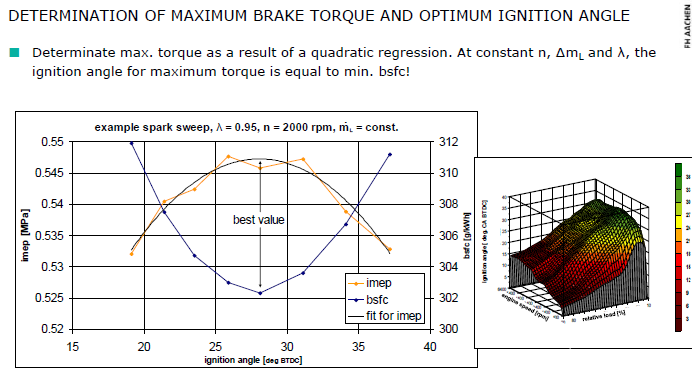
Image: the relation between spark advance and torque in a given operating point.
The first point to be calibrated before first firing the engine is the dwell time. It defines the charging time for the ignition coils and is controlled by the ECU depending on engine speed and battery voltage.
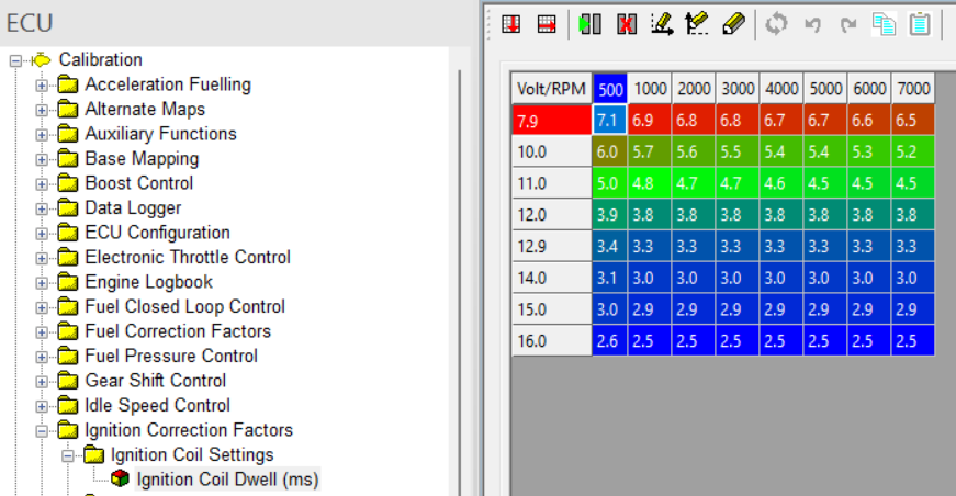
Image: the dwell table as calibrated in the
The basic ignition angle from the basic map needs to be corrected depending on a number of parameters:
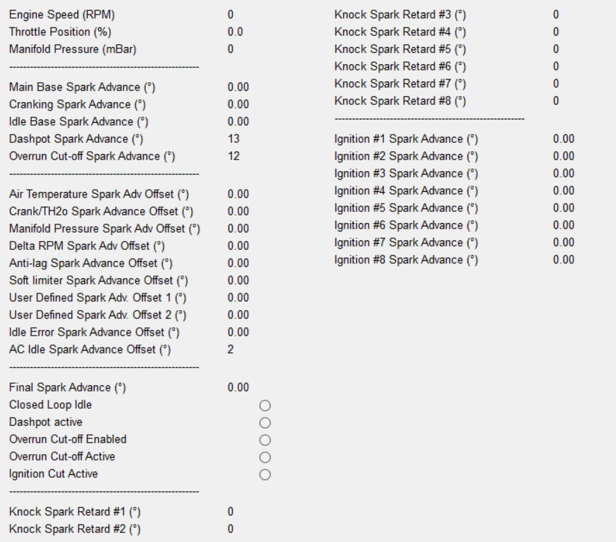 Image:
overview table of all spark advance calculation correction factors
Image:
overview table of all spark advance calculation correction factors
The first main correction is the one during engine cranking. In this mode, the base spark table is not used at all until the start mode is finished. During cranking the applied advance is taken from a specific crank advance table:
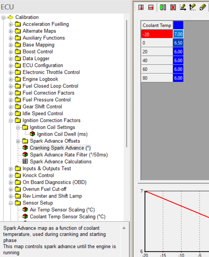
Image: cranking spark advance table as calibrated in the
Also in idle mode, the base spark table only acts as a maximum limitation and therefore is not directly controlling the applied spark advance.
The applied spark advance comes from a set target value for idle control plus the closed loop idle controller output to control the engine speed onto the idle target speed. A detailed description of this part can be found in the idle control chapter of this document.
In Part load and full load however, as soon as the idle control conditions are no longer met, the spark calculation will take the basic spark table values as its basic target setting.
These settings are then corrected to a number of boundary conditions of which the air temperature is the most important one:
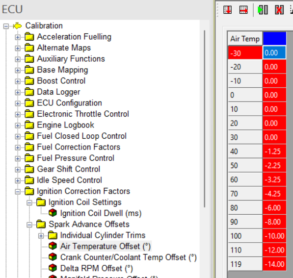
Image: intake air temperature depending advance correction as calibrated in the
Since the risk for knocking combustion increases considerably when the charge temperature is going up, the basic spark advance needs to be retarded. The same goes for increased coolant temperatures, they will lead to a higher combustion room temperature and therefore an increased risk for knock.
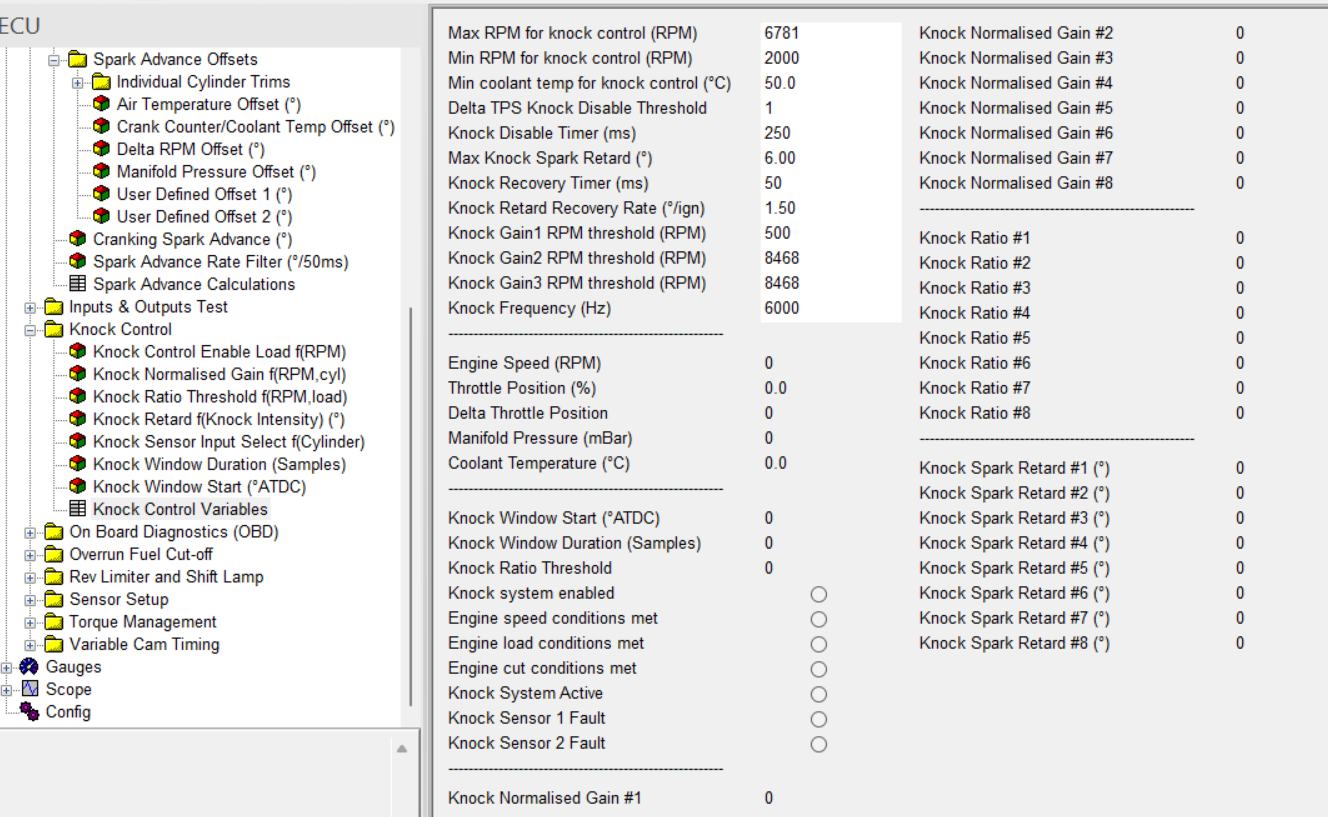
Image: knock control correction as calibrated in the
The next big spark advance correction is an active one coming from the cylinder specific knocking control function. For the specific functioning of the knock detection and control, see the next chapter but its output is an instantaneous cylinder specific level of spark retard to avoid knocking combustion on the following cycle. Therefore these retards need to be subtracted from the calculated spark advance instantaneously.
Besides the physically needed spark timing corrections handles so far, there are also a number of other reasons to change the spark timing under specific conditions. The main motivation behind these are driveability related.
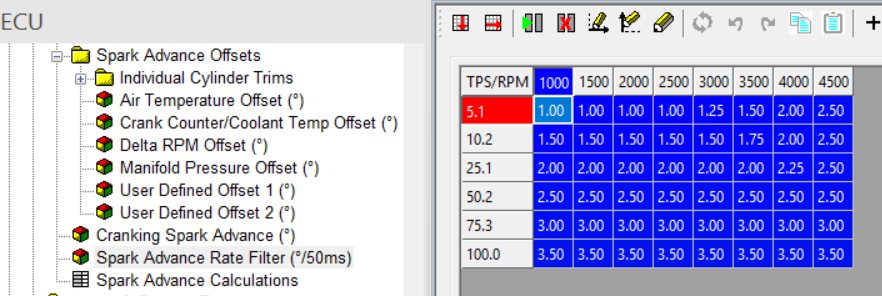
Image: spark advance rate limitation map as calibrated in the
On tip ins of the acceleration pedal, especially when coming out of idle, it can come to torque jumps that trigger an oscillation or load shock through the driveline and the vehicle. These create an unpleasant feeling for the driver and the passengers as well as an increase mechanical load on the driveline and powertrain.
Therefore, a number of driveability filters are in place.
The spark advance rate limiter, limits the rate of change on accelerations where typically the spark timing target jumps from a retarde idle value with torque reserve to an optimal part or full load spark timing. Unfiltered this would lead to torque jumps. By limiting the rate of change towards advancing the spark depending on engine speed and pedal angle, this initial shock can me limited or avoided completely depending on the desired characteristics of the car.
Whereas the spark advance rate limiter is more of a preventive nature, the second driveability function dltadv is more of a curative nature.
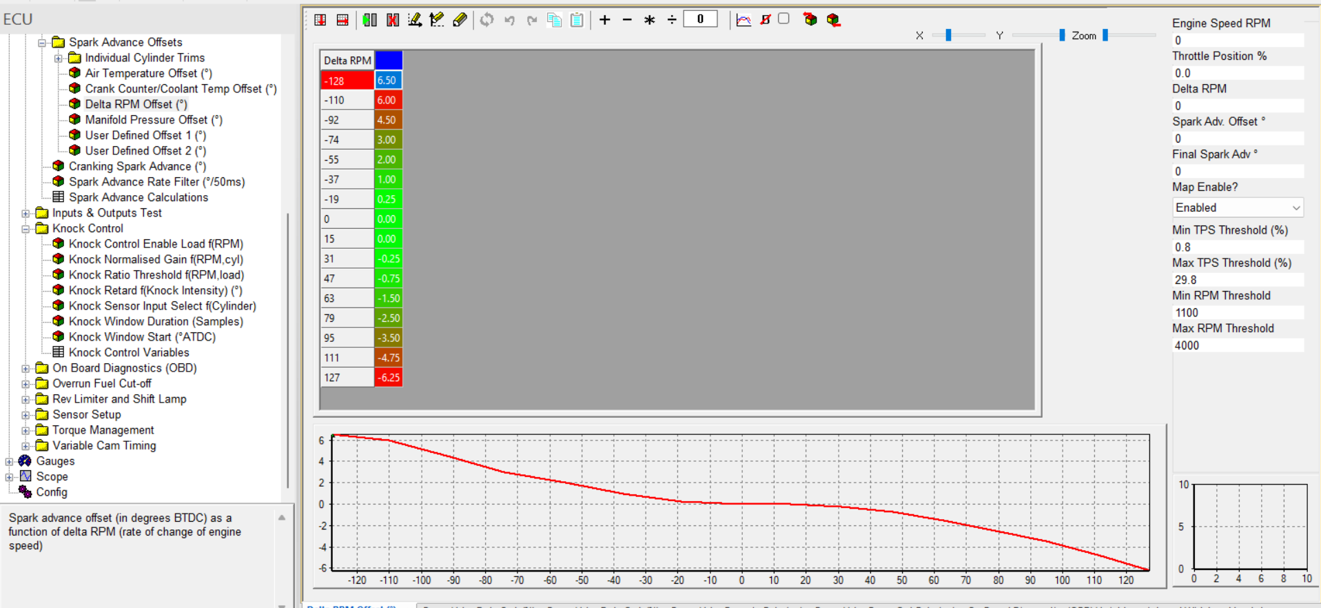
Image: dltadv spark advance anti jerk correction as calibrated in the
The dltadv function looks at the gradient of the engine speed and is searching for a pattern where a harsh acceleration phase is followed by a short deccelation and then an acceleration again. This pattern is an inidication of a torque oscillation or jerk in the driveline. These are often caused by the powertrain moving on its mounts against the limits and then returning to the opposite side of the mounts.
When this trigger condition is set, the dltadv function can counter this torque oscillation by building up a counterdirection torque correction over the spark advance. Retarding spark during acceleations and advancing it during decelerations. This can calm down and extinguish the original oscillation. The kind of correction is called active anti jerk control.
It is only active at low pedal values to not influence high load performance and also is typically only needed up to average engine speed values.