
Calibration & Control
Idle speed control
Set the mechanical/base idle correctly before asking closed-loop control to correct it.
Cable throttle without an idle-air valve
The existing SCS procedure uses spark advance to control idle speed. Warm the engine fully, balance multiple throttle bodies if fitted, disable closed-loop idle, and adjust the mechanical throttle stops so open-loop idle is roughly 50 RPM above the desired closed-loop target. Recheck fuelling and recalibrate TPS if the throttle stop has moved.
Set the Target Idle Speed map, then re-enable closed-loop idle using the TPS/PPS enable limit. In this configuration the ECU can correct warm idle with spark but cannot add airflow to achieve elevated cold-idle targets.
Idle valve / stepper applications
Where an idle valve or stepper is configured, the ECU parameter reference includes output frequency/stepper reset settings, base valve-position maps, proportional and integral gains, clamps and offsets for loads such as air conditioning and cooling fans.
Idle calibration maps
Use these with the guide below to establish a good base air setting and then tune the slow air-path and fast spark-path corrections without oscillation.
Idle control strategy
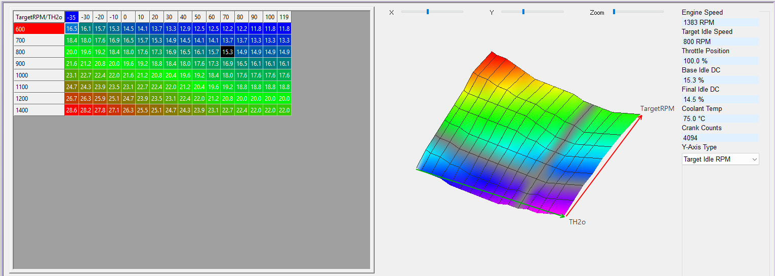
Set Target Idle Speed: The target idle speed should first be set in the Target Idle Speed (rpm) map. A typical map is shown below. The idle speeds shown for temperatures below normal operating temperature will not be achieved (since spark advance is the only method the ECU has to adjust the idle speed). The can be set to the open loop idle speed when warm. Temperatures encountered under normal conditions should be set to the desired idle speed. Commonly this can be around 1000 RPM for example for a mini.
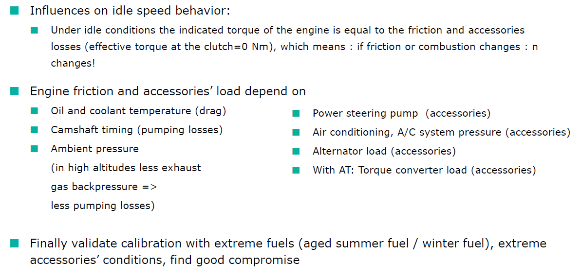
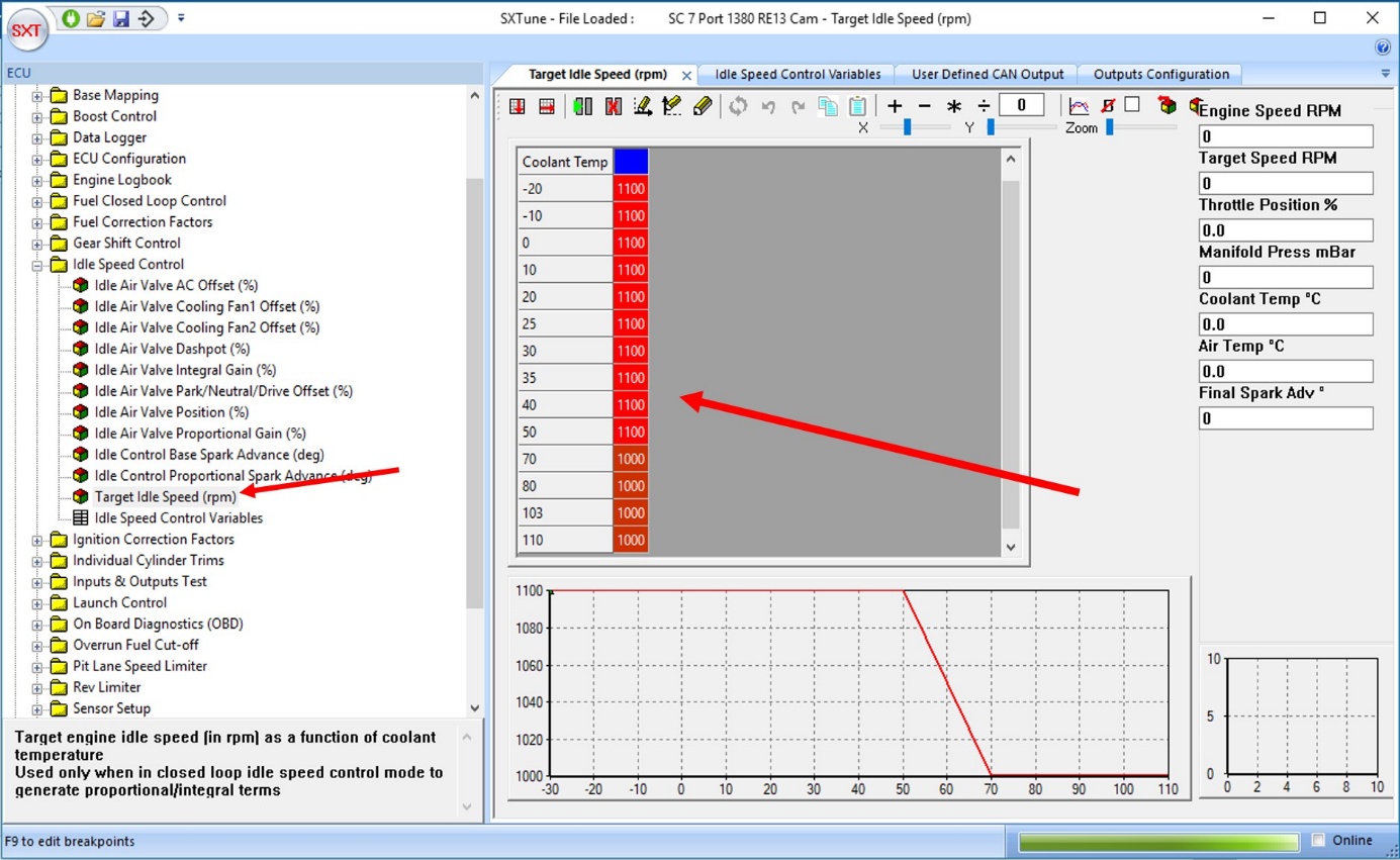
Image: target idle speed map over coolant temperature
Closed loop idle control can now be turned on by setting the Idle Control TPS/PPS enable limit (%) to 0.8. Closed loop control will now alter spark advance as necessary to achieve the idle speed set in the map (for normal operating temperatures)
The next maps to be calibrated are the target spark advance in idle and the idle air valve position. By setting the target spark in idle, you control the so called torque reserve. In idle we do not operate the engine at optimal spark efficiency to maintain a certain reserve in torque used by the idle controller to maintain stability. The picture below shows this well.
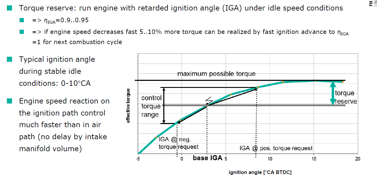
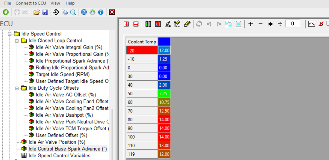
Image: idle control base spark map
This map sets the target spark advance in idle. The airpath will try to control the engine load in order to achieve this target spark advance in closed loop idle.
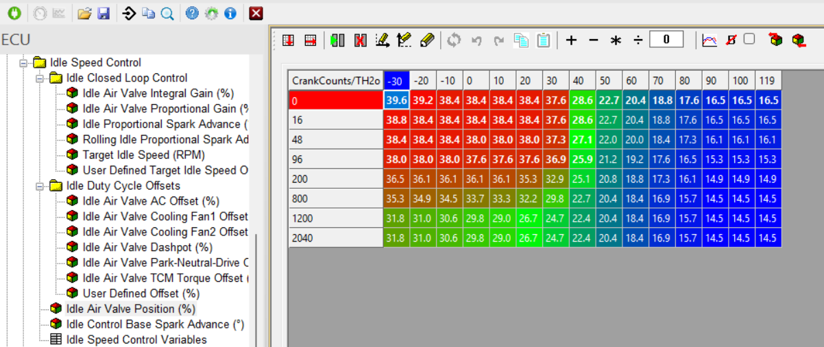
Image: idle air valve postion
This map sets the precontrolled airmass for the the idle controller and as such is also the minimum position of the throttle. It needs to be calibrated in such way that the closed loop idle controller needs to be only perform a minimal correction. The outcome of this map together with all the other compensation maps for the different load consumers forms the base idle duty cycle in %.
As visible in the picture below, this base idle duty cycle then gets added to all the closed loop air path corrections as well as the dashpot compensation air amount.
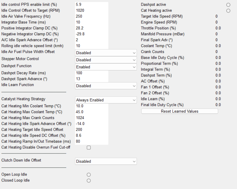
Image: idle air valve postion
A next step in the calibration process is then to calibrate all the separate load compensation maps such as the one for AC, for the gear/ torque converter on automatic cars and for the fan control and alternator load.
Once all the precontrolled load compensations are calibrated, the closed loop controller needs to be calibrated. It is a traditional PI closed loop controller but there is one acting only on the slow air path and another P controller acting on the fast torque spark path.
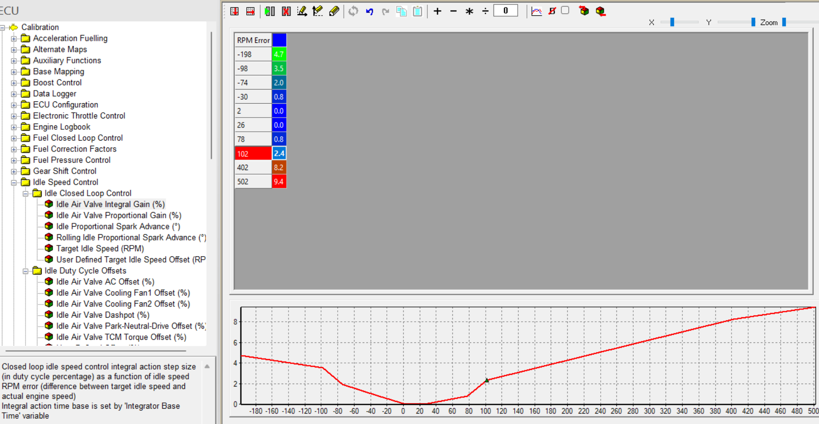
Image: idle closed loop controller integrator gain
The integrator gain is multiplied with the idle speed error and then goes against that deviation by adding air when the speed is below target and subtracting air valve duty cycle when the engine speed Is over the set target speed.
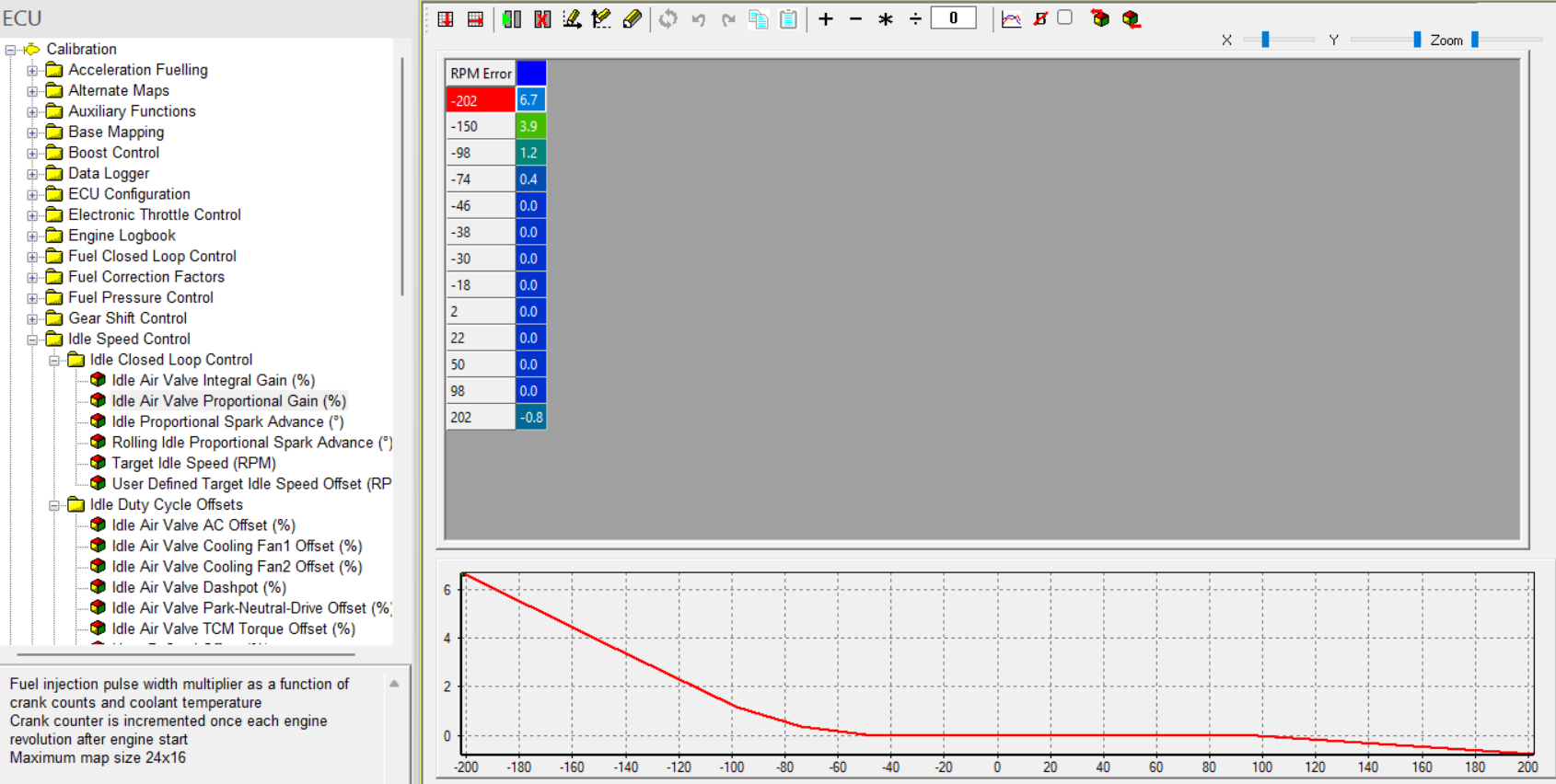
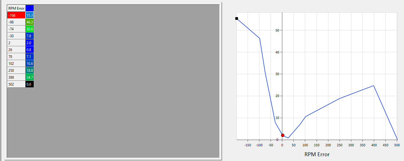
Image: idle closed loop controller proportional gain
The proportional gain is also multiplied with the idle speed error and then goes against that deviation by adding air when the speed is below target and subtracting air valve duty cycle when the engine speed Is over the set target speed.
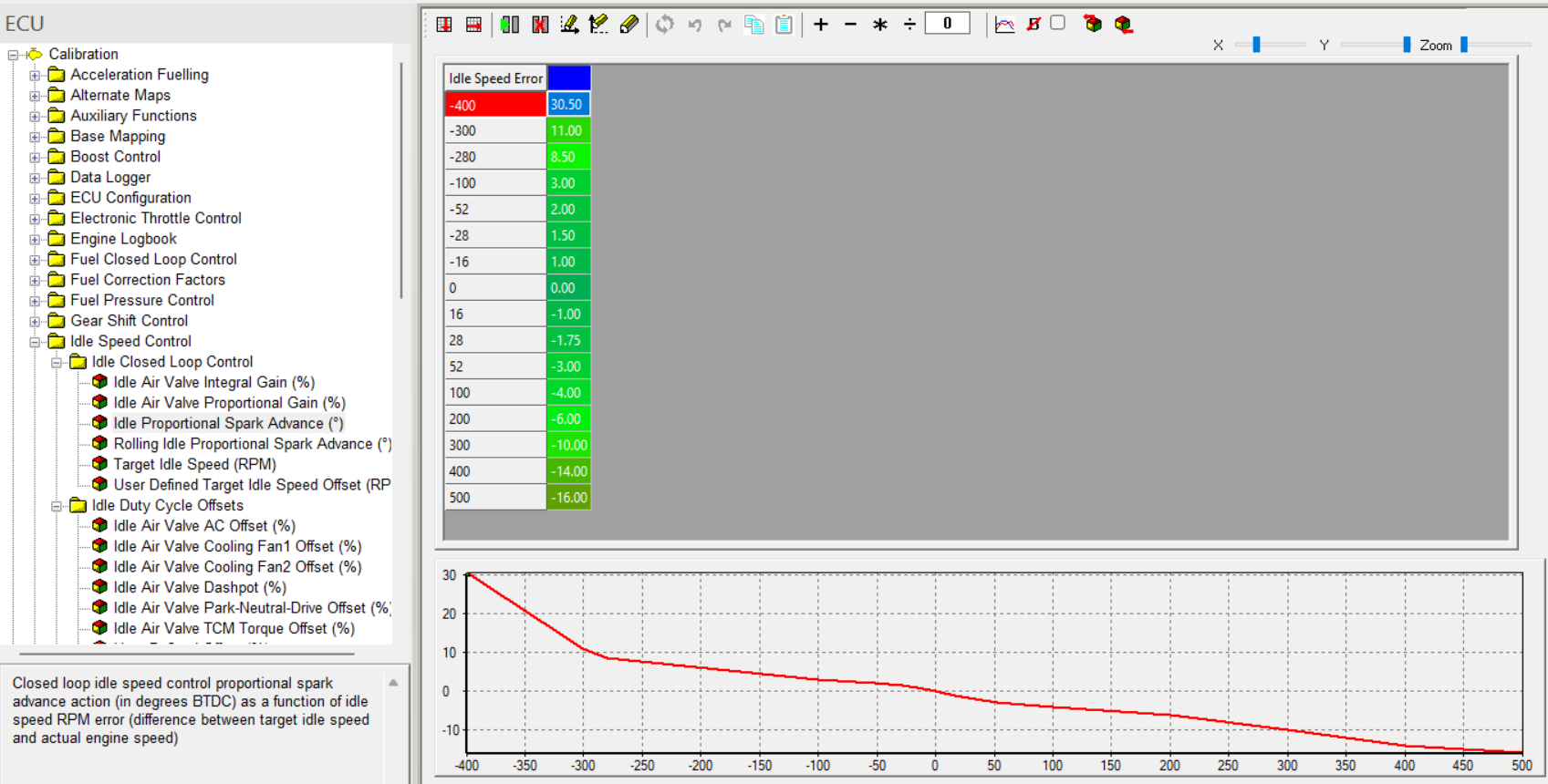
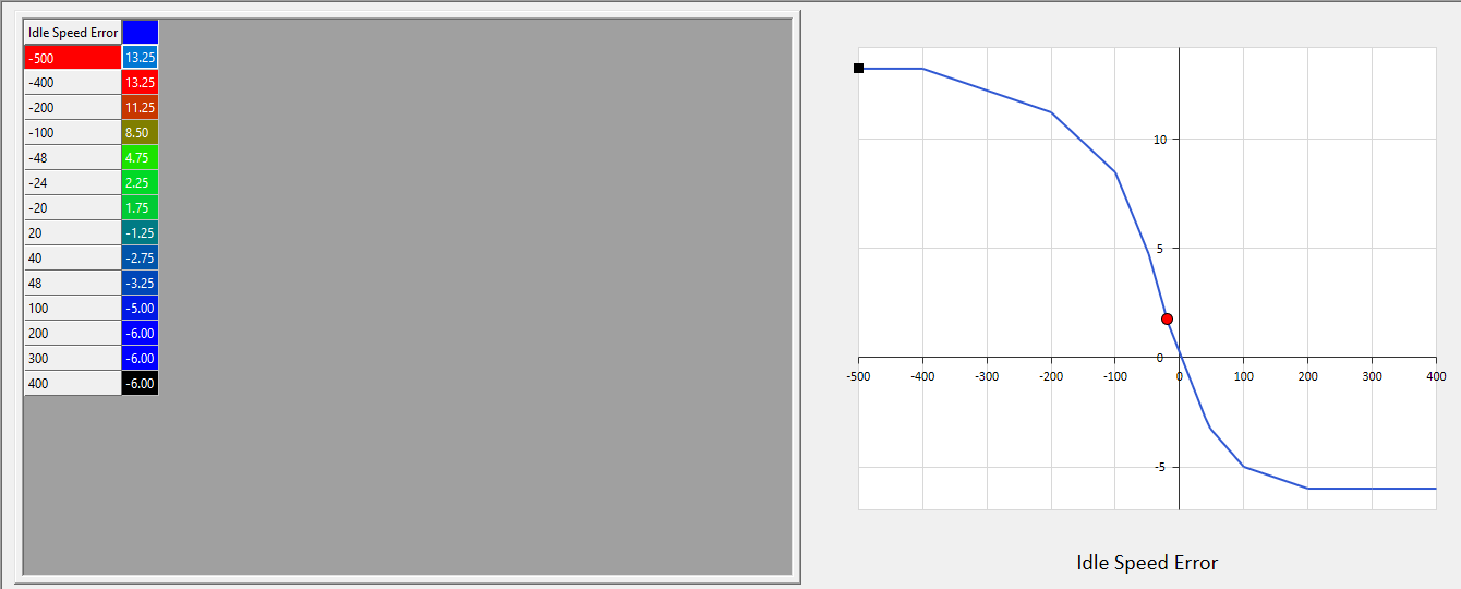
Image: idle closed loop controller proportional gain for the spark advance, quick path
A second proportional gain is also multiplied with the idle speed error and then goes against that deviation by adding spark advance when the speed is below target and retarding the ignition angle when the engine speed Is over the set target speed. This control is quick acting because it can alter the engine torque in between two combustion cycles immediately.
For all of these controller gains, the general rule applies to make them as strong a possible without creating big control overshoots or oscillations. For rolling idle, a second set of gain parameters can be activated since the inertia of the powertrain is then bigger and integrator wind up could become an issue with the more aggressive standard idle gains.
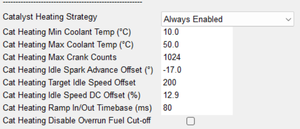
Image: catalyst heating control
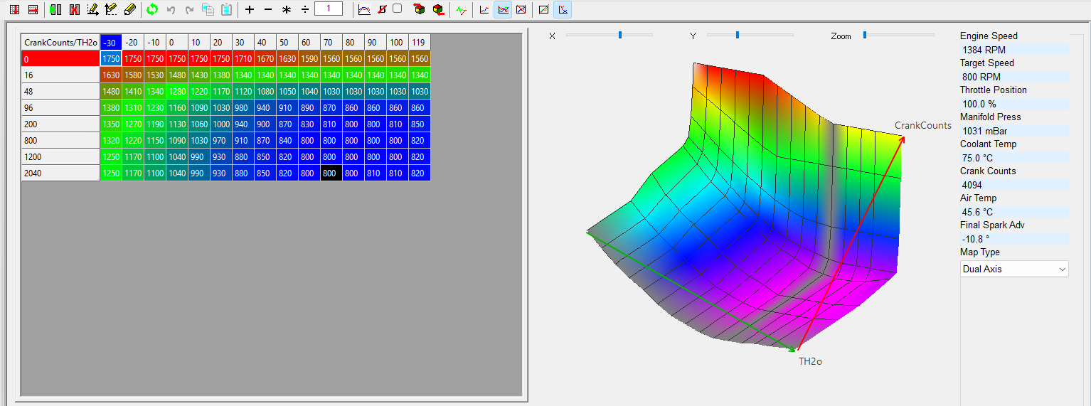
Inside the idle control function, you will also find the catalyst heating control function. It can be triggered directly after start depending on the coolant temperature at start. It then becomes active for a number of crank counts until the catalyst reaches operating temperature.
The strategy exists out of two parts;
The first one increases the idle speed target to produce more exhaust gas flow to transport heat into the catalyst.
The second one retards the ignition as far as the combustion stability of the engine will allow in idle to decrease the thermal efficiency of the combustion and thus produce hotter and more exhaust gasses which will then transport more thermal energy towards the catalyst.
This function is typically only needed for about 800 to 1000 crank counts after start after which it is ramped out over a calibrateable ramp. At this point the catalyst has reached its light off temperature.
Since for both the increase idle speed and for the retarded spark, more air is needed by the engine an offset to the normal base idle DC is active during catalyst heating and needs to be calibrated here.
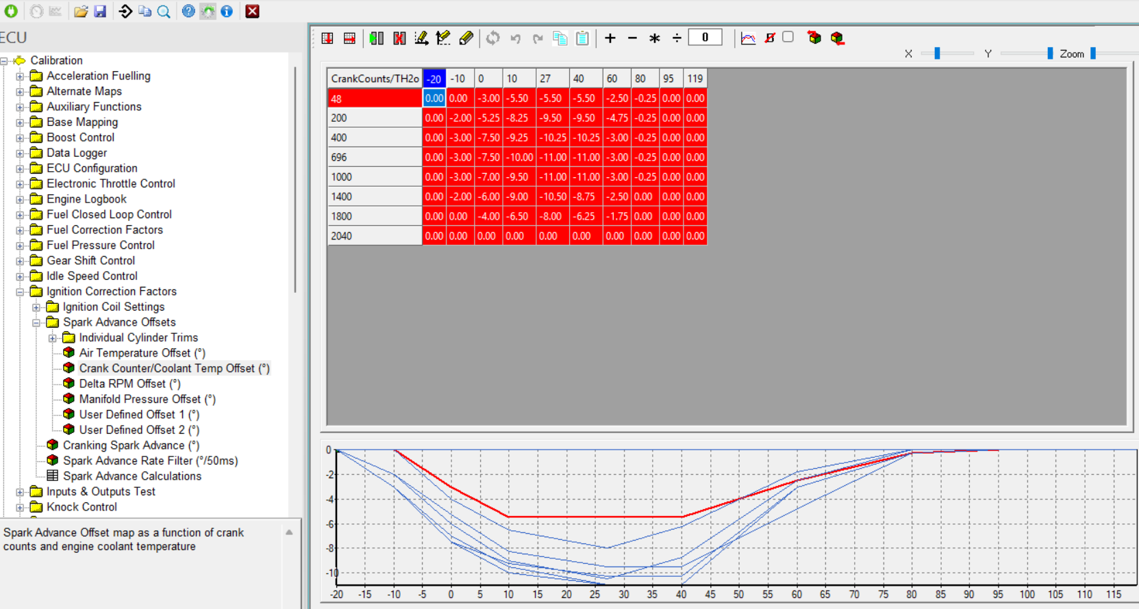
Image: catalyst heating spark retard table for cold part load operation
A second part of the catalyst heating strategy is inside the ignition correction factors function. It retards the ignition angle on cold part load acceleration to further assist the catalyst light off process. This function is also needed to reduce the aggressivity of the torque increase when leaving the catalyst heating idle which has lots of torque reserve over spark retard and go into part load operation. Without retarded values inside this map, the spark advance would immediately jump to its optimal value which due to the excessive amount of air/ manifold pressure would lead to a big jump in torque.
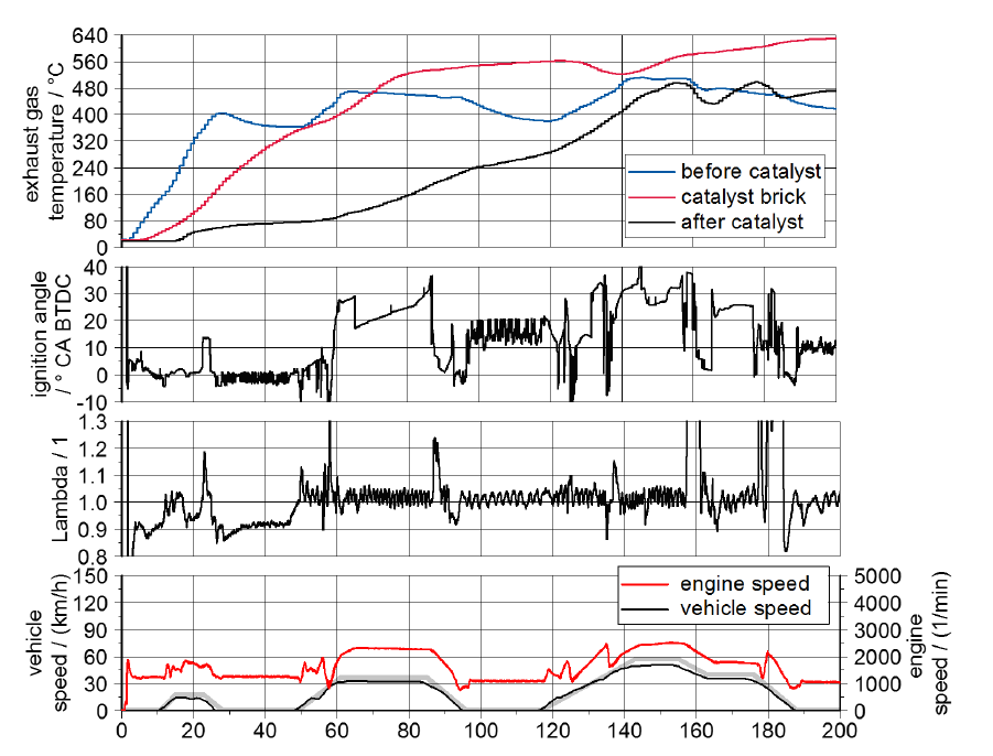
Image: catalyst heating phase in an emission cycle.