Calibration & Control
Turbo boost control
Set a safe open-loop wastegate duty first, then use target pressure and PI correction for closed-loop control.
How the strategy is organised
The existing SCS guide describes four principal calibration elements: Base Duty Cycle, Target Manifold Pressure, Integral Gain and Proportional Gain. Base duty establishes the underlying wastegate-solenoid command; target pressure defines the requested manifold pressure; proportional and integral terms correct the error between target and measured pressure.
Recommended calibration sequence
- Confirm the boost-control solenoid is wired to the configured PWM output and that its operating frequency is correct.
- Temporarily disable closed-loop boost correction.
- Calibrate Base Duty Cycle across the intended RPM/load range so boost remains safe everywhere.
- Set the desired Target Manifold Pressure map.
- Enable closed-loop control and assess tracking and stability.
- Only adjust proportional/integral gains when required to correct slow response or oscillation.
Boost Control pages
Calibrate the open-loop base duty first, then the target pressure and finally closed-loop behaviour. The live variables page lets the base and final duty, target, error and controller state be checked together.
Boost control strategy
Boost control is achieved by means of a bleed valve in the turbocharger wastegate controlled by a Pulse Width Modulated (PWM) signal from one of the ECU PWM outputs as selected in ECU configuration.
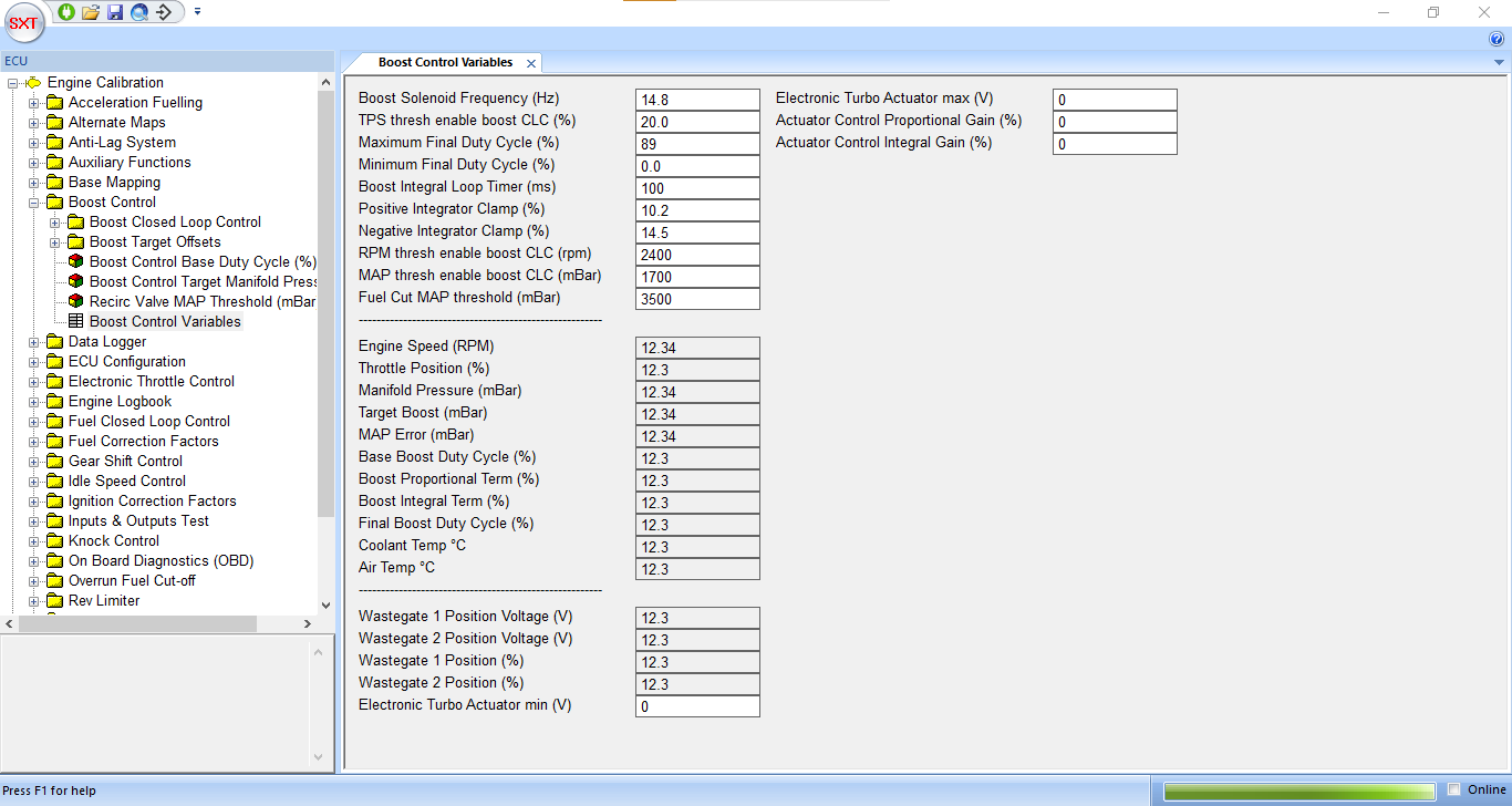
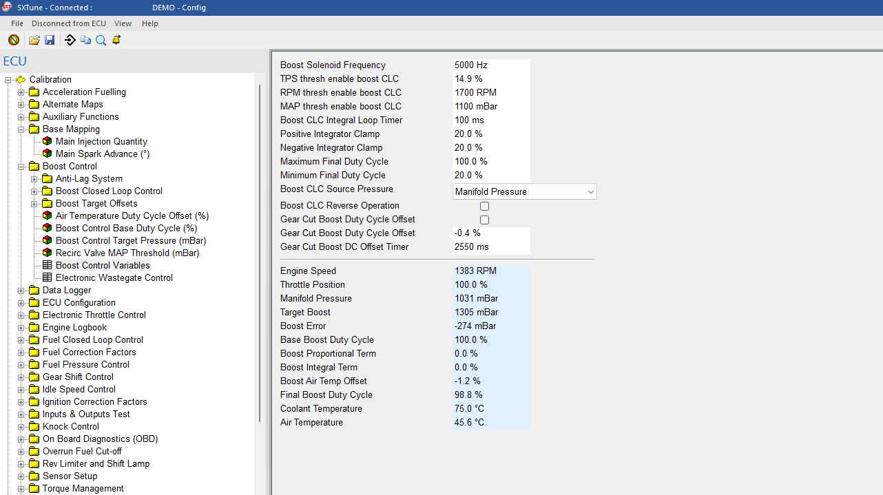
This Boost Control page displays values relating to the closed loop boost control strategy and is broken down into:
Boost Solenoid Frequency – The piloting frequency at which the boost control solenoid will be driven in Hz.
TPS Thresh enable boost CLC – the throttle position percentage above which the closed loop boost control strategy becomes active (set to 99.45 to disable closed loop boost control)
Maximum Final Duty Cycle – The maximum boost control solenoid duty cycle percentage
Minimum Final Duty Cycle – The minimum boost control solenoid duty cycle percentage
Boost Integral Loop Timer (ms) – The time base for the boost PI controller integral term
Positive Integrator Clamp (%) – The maximum positive value of the boost PI controller integral term
Negative Integrator Clamp (%) – The maximum negative value of the boost PI controller integral term
RPM Thresh enable boost CLC – the engine speed above which the closed loop boost control strategy becomes active.
MAP thresh enable boost CLC – the MAP sensor value in mBar above which the closed loop boost control strategy becomes active.
Fuel Cut MAP Threshold – the map sensor output in mBar at which fuel delivery will be completely turned off (for engine protection purposes).
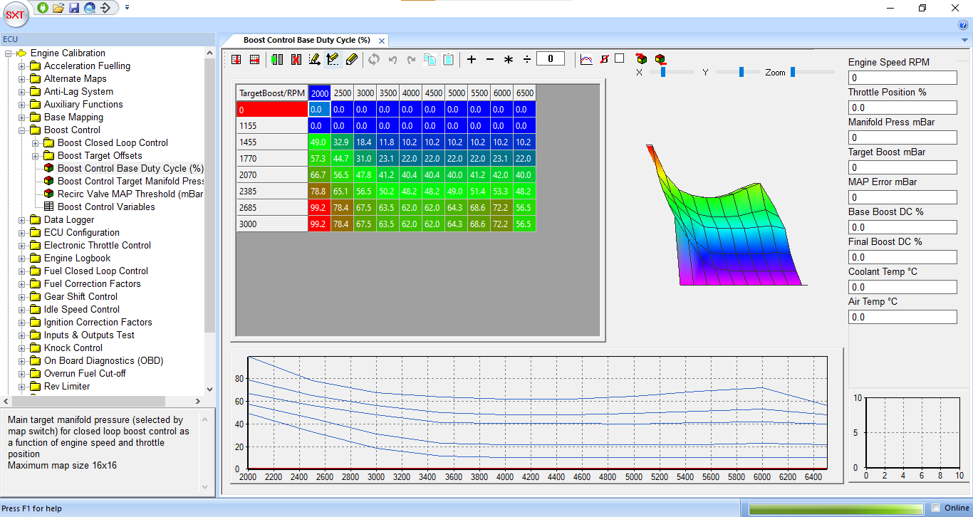
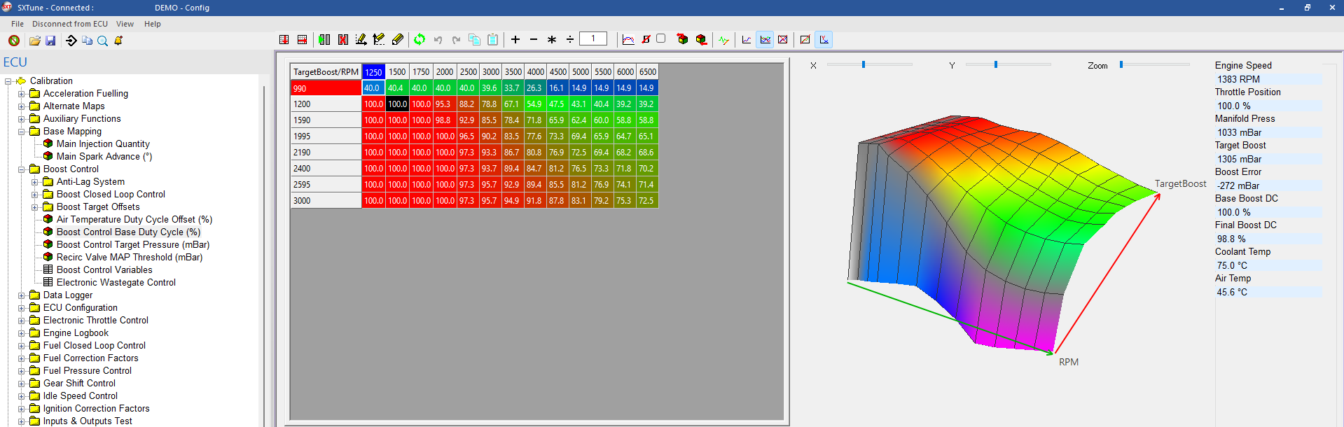
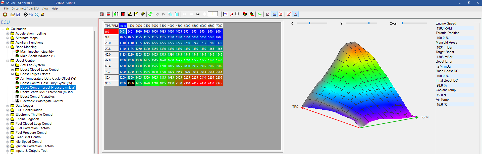
The open loop boost control term is calculated by a map as a function of throttle position and engine speed. This should be calibrated to achieve the target boost level before closed loop boost control is enabled. The target manifold pressure in mBar is calculated from a map also as a function of throttle position and speed.
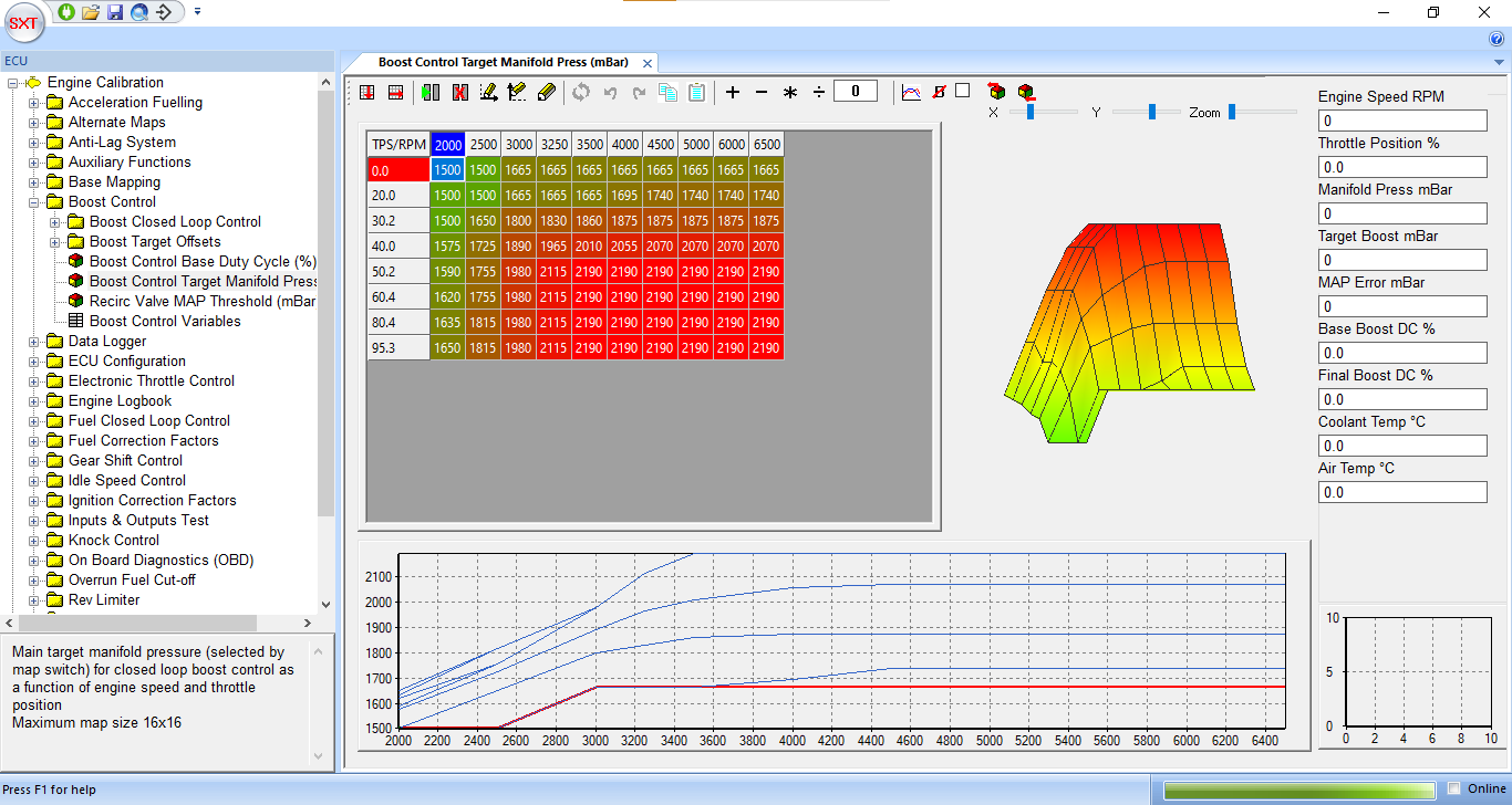
The open loop boost control term is calculated by a map as a function of throttle position and engine speed. This should be calibrated to achieve the target boost level before closed loop boost control is enabled. The target manifold pressure in mBar is calculated from a map also as a function of throttle position and speed.
Engine Logbook
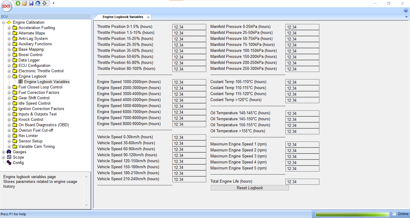
The engine log book provides min/max and time spent at/above values for a variety of parameters. It also stores the 5 highest engine speeds attained to allow quick identification of engine over rev. It can be reset at any time by clicking the ‘Reset Logbook’ button.
Data Logging Function: The gauges page also provides a data logging function for recording, playing back or exporting as a .csv data shown on the gauges. This function is controlled via six buttons on the lower left of the screen which provide functionality for playback, recording, fast forwarding, rewinding, stopping and pausing the data logging. To export the data as a .CSV file (which can be imported directly into MS Excel) right click on a gauge and select the “Save Data To CSV” option or click ‘Record’ in the File Menu.
Rev Limiter
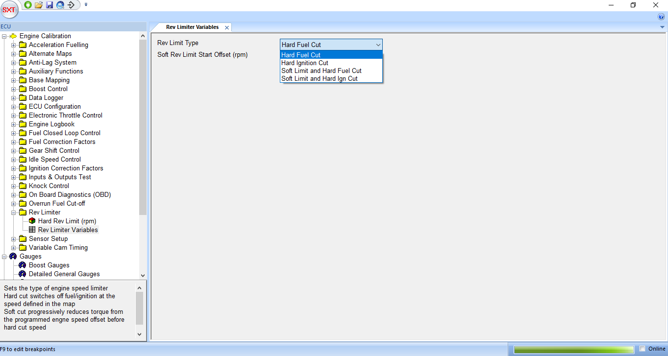
Rev limiting (over-speed protection) is implemented by a user selectable range of hard and soft cuts. The primary hard rev limit is set by a Map ‘Hard Rev Limit (rpm)’ under the Group ‘Auxiliary Functions’. This map is a function of coolant temperature, enabling a reduced rev limit to be set when the engine is too hot or too cold providing increased engine protection.
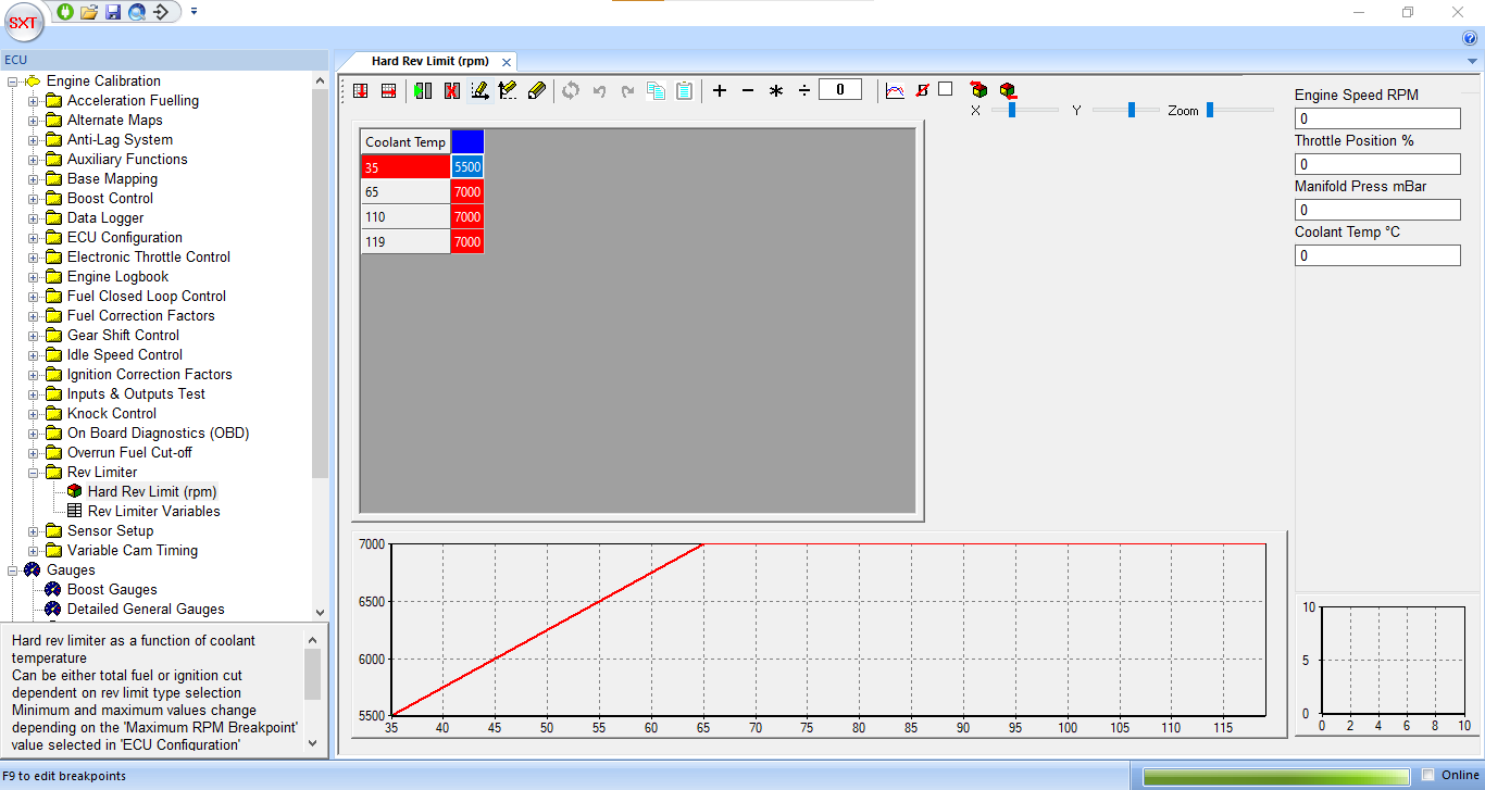
The rev limiter type is set by a drop-down box in the ‘Rev Limiter’ Variables page. There are options of hard fuel or ignition cuts, where either the fuel injection or ignition is completely switched off when the engine speeds exceeds the value obtained from the ‘Hard Rev Limit’ map. Also available is a soft limit which progressively reduces the engine torque as the hard limit is approached, giving a much smoother rev limiting effect. The start of the soft limiter is set by the value ‘Soft Rev Limit Start Offset (rpm)’ as an offset to the hard cut value. For example, if the hard cut is set to 8000rpm and the soft rev limit offset to 250rpm, the ECU will begin to reduce the engine torque at 7750rpm, increasing to a 50% reduction in torque at 7875rpm and culminating in a complete cut at 8000rpm.