
Map Editor
Edit tables, breakpoints and live calibration values.
Using SXTune
The SXTune layout, principal toolbars, menus and working areas.
The main toolbar provides quick access to the most commonly used connection, calibration and application commands. The icons shown below are the actual SXTune toolbar icons.



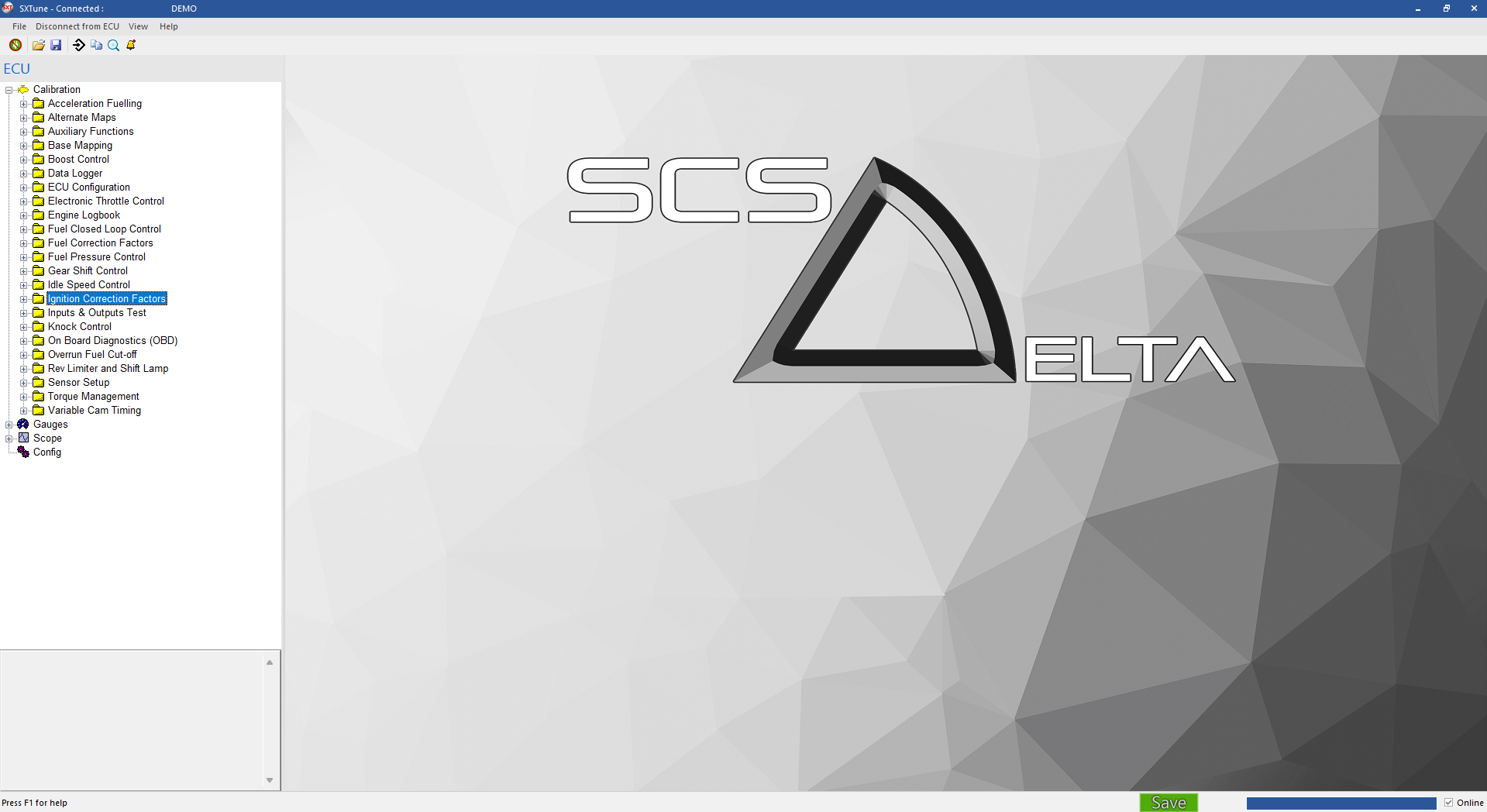
The View menu controls the status bar and tab grouping. Map Editor chart options are context-sensitive, so some entries are disabled unless an appropriate Map Editor page is active.
Launch the help site, check for application updates, or open the About dialog.
Edit tables, breakpoints and live calibration values.
Preset and custom live displays.
Time-history plotting, triggering and replay.
This page describes some of the parameter groups found in the SXtune software and how ECU outputs (e.g. injection pulse width) are calculated from the parameters. Because the ECU is highly configurable, the customer is advised to familiarise themselves with parameters and how they combine to effect the outputs (e.g. injection pulse width, boost etc) they are interested in calibrating. There is also a description of some of the editing features.
Map Editor
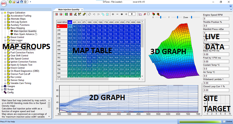
The Map Editor provides access to the maps used for calibration of the ECU. Specific maps are organised into groups selected by the right hand drop down and individual maps are accessed via the left hand drop down. A 3D graph of the map is shown to the right of the main map editor table and a 2D representation of rows/columns is shown under the main map editor table.
Map Editor ToolBar: The Map Editor Toolbar provides
access to the cell operations listed below.

Interpolate Cells: The interpolate function
automatically fills in cell values into the map in either rows or
columns with linear interpolated values between the first and last
cells.

Breakpoint Editing: Breakpoint editing mode for the
X and Y axes is enabled by clicking the appropriate icon showing the
axis to edit. To return to the main map editor click the breakpoint icon
with no axes.

Insert/Delete Breakpoints: Inserting and deleting
breakpoints is only enabled in breakpoint editing mode. To insert a new
breakpoint select the point for insertion in the map and click the
‘Insert Breakpoint’ icon. The map will be fully recalculated to insert a
new breakpoint with linear interpolated values in the new cells. To
delete a breakpoint, select the breakpoint to be deleted and click the
‘Delete Breakpoint’ icon. By modifying breakpoints in this way, changes
will not affect the existing calibration.

Undo and Reset: The last change made to a map can be
undone by clicking the ‘Undo’ icon. The whole active map can be reset
to the state at ECU power-up by clicking the ‘Reset’ icon.

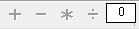
Mathematic Operators: The maths operators – add,
subtract, multiply and divide are available for the selected cell or group of cells. For example, to multiply the selected cells by 1.2 (increase by 20%), enter 1.2 into the maths box and click
the ‘*’ icon.
Change 2D Plot Type: This icon changes the 2D plot
through the following sequence: ‘Plot all rows’, ‘Plot selected row
only’, ‘Plot all columns’, ‘Plot selected column’ allowing all aspects of
the map to be viewed as a 2D slice.

Clear Bold Text in Cells: Cells that have been
modified in the active map are highlighted in bold text. To clear all
the bold text, click this icon.

Lock Trace Cell: To force the focus cell to be the
trace cell, tick this box. This avoids needing to press the
space bar to make the focus cell jump to the trace cell. This
function will stop the user from selecting other cells or groups of
cells for editing; only the trace cell can be edited. To return
to normal editing mode un-tick the ‘Lock Trace Cell’ box.

Keyboard Functions: Within the map editor tab changes are made either by typing a value into the load site or using PgUp and PgDwn keys to increase or decrease the values. Load sites are selected with the mouse, arrow keys (if the focus is set on the table) or by pressing the space bar which will select the active load site.
A full break down of keyboard commands used in the Map Editor tab is provided below:
Function Keys:
F1 – Help
F2 – Move Forwards Between Maps within a Group i.e. between main fuel map and main ignition map
F3 – Move Backwards Between Maps within a Group
F5 – Refresh (reload) Active Map
F8 – Edit Y Axis Break Points
F9 – Edit X Axis Break Points
F10 – Open File Menu
F11 – Return to map editing from breakpoint editing
Shortcut Keys:
CTRL + S – Save Active Map To File
CTRL + L – Load Active Map From File
CTRL + Q – “Quick Fuel” Function (See Quick Fuel Section Below)
CTRL + PgUp – Coarse Adjust Value Up
CTRL + PgDwn – Coarse Adjust Value Down
SPACE – Jump to Trace Cell
Editing Keys:
PgUp – Fine adjust value up
PgDwn – Fine adjust value down
Quick Fuel:
Quick fuel is a method for rapidly setting fuelling whilst the engine is in steady state. Quick Fuel is only available if the ECU has a wideband Lambda Sensor connected, closed loop fuelling is turned on and the target lambda table is calibrated.
To use Quick Fuel hold the engine on a load site, ensure the target is as close to centre as possible. Wait until the closed loop compensation has stabilised at a value and press CTRL+Q. When CTRL+Q is pressed SXTune will adjust the active load-site injector pulse width based on the displayed value + or – the amount of closed loop lambda adjustment. When Quick Fuel has been activated on a load site the closed loop fuel correction should now read zero.
Quick Fuel is intended as a tool to help rapid calibration of low load and engine speed load sites. Its use should be limited at high engine speeds and care should be taken when using Quick Fuel to validate that the entered value is sensible and correct. It is always recommended that a Dyno lambda sensor or similar is used as well as an on-vehicle lambda sensor to validate the on-car reading.