
Calibration & Control
Fueling Calculations
Understand how the ECU calculates fuel quantity and calibrate the primary fuel map and its corrections.
Primary load and the fuel map
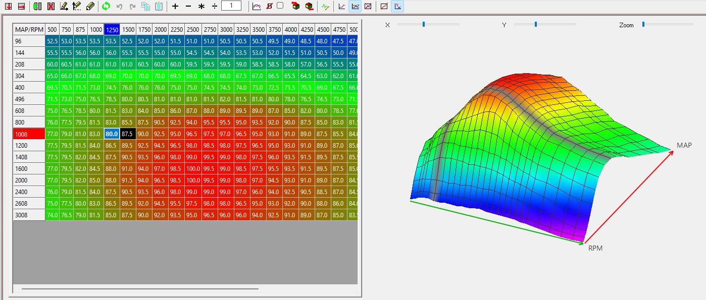
The Base Mapping group contains the primary fuel map. Its load axis is either throttle position or manifold pressure according to the ECU's primary-load configuration.
In pulse-width mode the main fuel map is scaled against the configured maximum injection pulse width. The existing SCS mapping notes describe the table as 255 steps from 0–100% of that maximum, so an unnecessarily large maximum pulse width reduces low-load resolution. In volumetric-efficiency mode the fuel calculation is different and requires MAP and injector-flow information.
Recommended workflow
- Complete sensor, trigger, injector and ignition configuration before mapping under load.
- Confirm the engine is synchronised and commanded ignition timing agrees with timing measured at the engine.
- Establish safe fuel and ignition values before enabling strategies which can add boost or significant torque demand.
- Map steady-state fuel and ignition over the required speed/load region.
- Use measured lambda/AFR and appropriate dynamometer instrumentation to validate the result.
- Only after the base maps are close should closed-loop lambda and transient corrections be used to refine operation.
Quick Fuel
SXTune's Quick Fuel function can update the active fuel load site from the stabilised closed-loop lambda correction. It requires a working wideband sensor, closed-loop fuelling and a calibrated target-lambda table. The existing SCS documentation recommends it for steady-state, lower-load calibration and warns that entered values must still be checked for plausibility, particularly at high engine speed/load.
Main fuel map
Desired fuel mass calculation
From the calculated air volume, we then calculate the air mass flow going into the engine in kg/h using the mol mass of air.
This calculated air mass is then taken as the basis to calculate the required amount of fuel mass which needs to be injected to reach the targeted lambda value. The target lambda is taken into account as Lstoich (14.5 for gasoline) for lambda equals 1 and an additional direct multiplication factor for all other target lambdas as well as all the different open loop control enrichment factors.
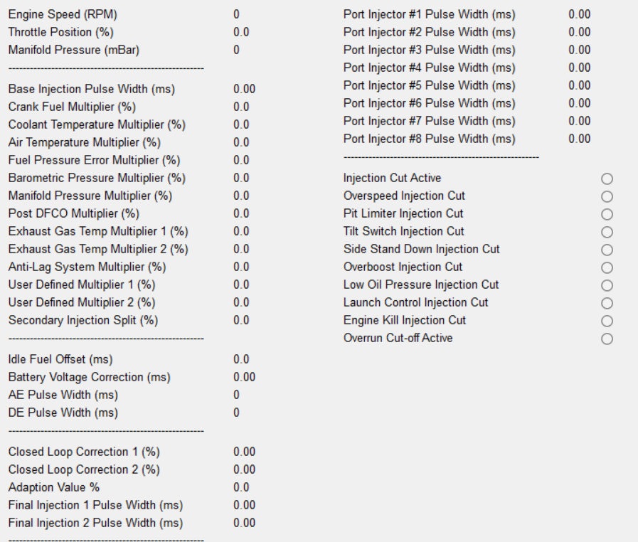
Image: overview of all possible enrichment factors going into the fuel quantity calculation
The base injection pulse with is the injection pulse resulting out of the basic calculation from Volumetric efficiency into total airmass flow and multiplied with the basic Lstoich multiplier for the target lambda.
The crank fuel Multiplier is a direct multiplier for the open loop fuel quantity depending on the coolant temperature and the number of crank counts since the first combustion after synchronization. This enrichment factor is needed to compensate for wall film losses and poor fuel evaporation on the cold engine.
It needs to be calibrated in such a way that every single combustion after synchronization is stable without any stumbling or risk for misfire, while at the same time not being too rich.
At high coolant temperatures, this map can be used to compensate for hot fuel boiling issues by adding higher factors.
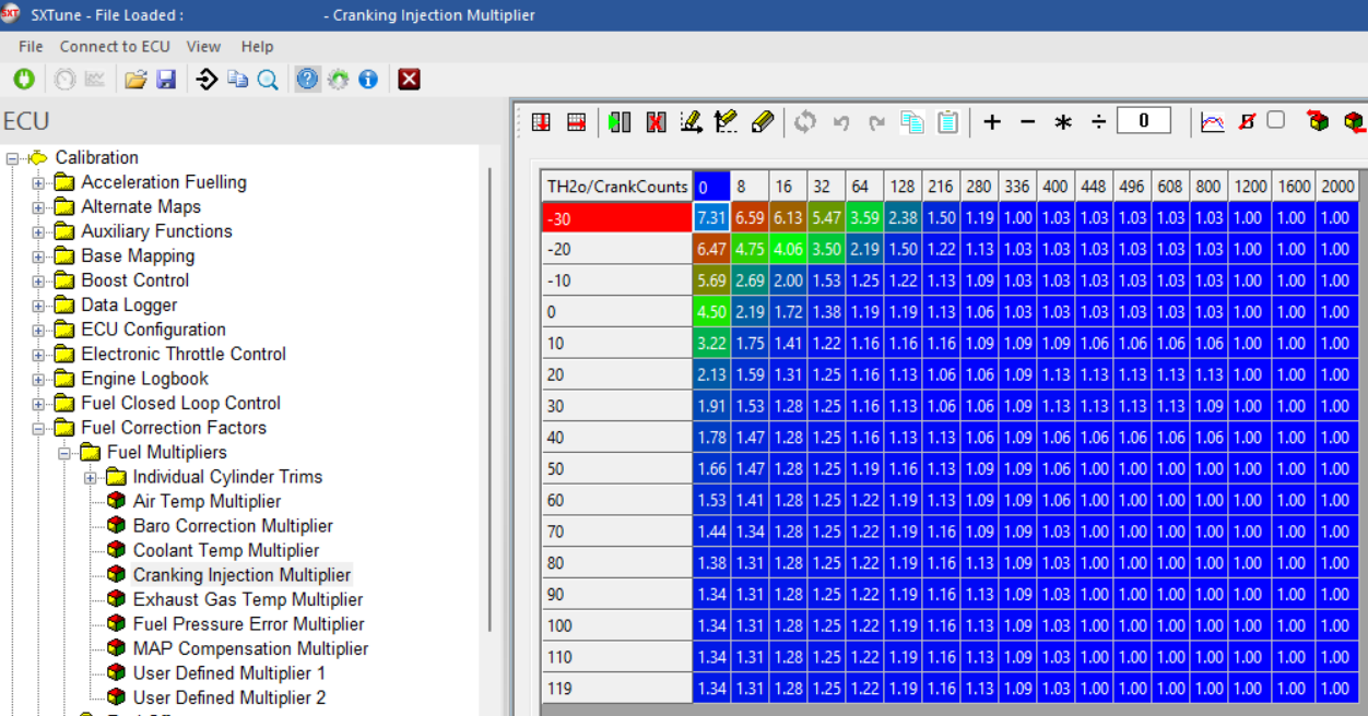
Image: an example of a crank injection map as calibrated for V6 PFI engine.
The coolant temp Multiplier is a direct multiplier for the open loop fuel quantity depending on the coolant temperature. This enrichment factor is needed to compensate for wall film losses and poor fuel evaporation on the cold engine during the entire warm up phase. This needs to be calibrated in such a way that the combustion is stable and near the target lambda when the closed loop controller is not yet available or afterwards in such a way that the CLC has very little to no need to correct the fueling.
At high coolant temperatures, this map can be used to compensate for hot fuel boiling issues by adding higher factors.
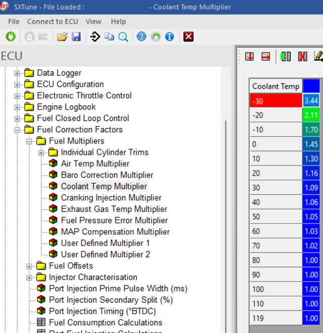
Image: an example of a coolant temperature compensation map typical for V6 PFI turbo engine.
The air temperature, atmospheric pressure and intake manifold pressure multipliers do not need to be used when applying the volumetric efficiency mode since they are already taken into account in the calculation of the basic VE. They are tied to the laws of physics.
The post DFCO (deceleration fuel cut off) enrichment is a very specific enrichment function which is used to compensate the lost wall film during the reinjection phase following fuel cut phases. Depending on how long the fuel cut phase was (in number of missed injections), we go up with an initial value for the reinjection enrichment. It is then ramped out again over the number of performed injections after the DFCO.
In this way we can make sure that the very first injections after a DFCO also burn well without creating additional Nox emissions or lean misfire.
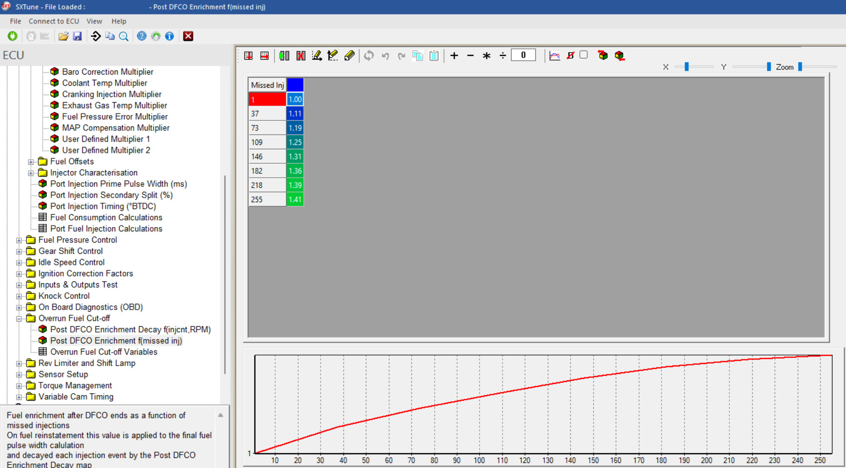
Image: an example post DFCO enrichment map typical for a PFI engine, giving the initial enrichment factor depending on the number of missed injections, as calibrated in the .
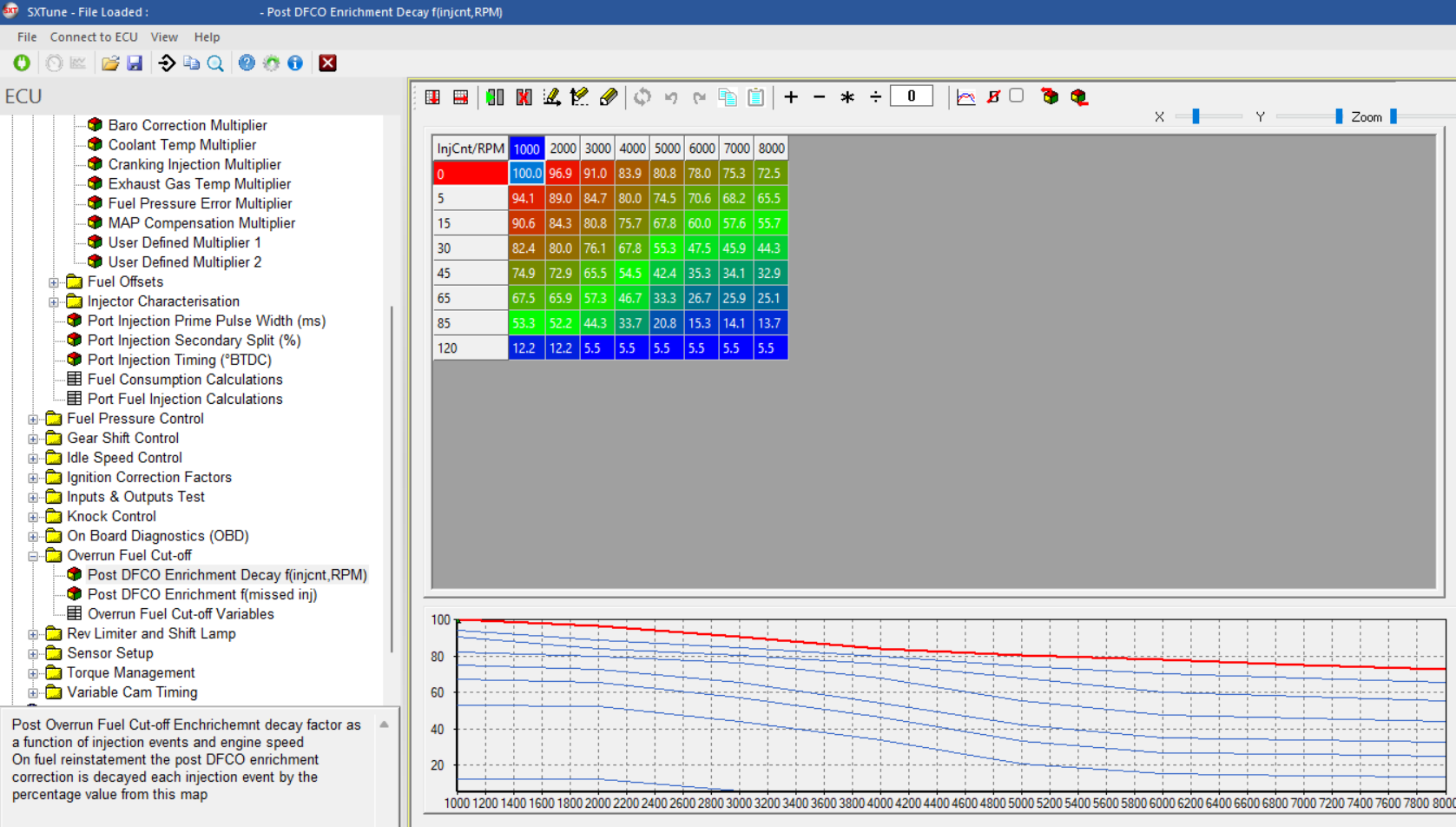
Image: an example post DFCO ramp down map for the PFI V6 turbo engine, giving the decay of the initial enrichment depending on the number of performed injections after the reinjection.
The multipliers for EGT (Exhaust Gas Temperature) are optional if you want to have an EGT depending open loop enrichment.
The same effect can be achieved closed loop as well, when the option for taking into account the target lambda is used. The target lambda needs to be calibrated rich in areas where the exhaust gas temperature becomes critical as explained elsewhere in this document. The factor of enrichment from the richer target lambda is then automatically multiplied with the basic fuel quantity.
The user defined multipliers can be used for a large number of different reasons. For example in a flexfuel system, we can correct for the lower fuel density depending on the alcohol level here.
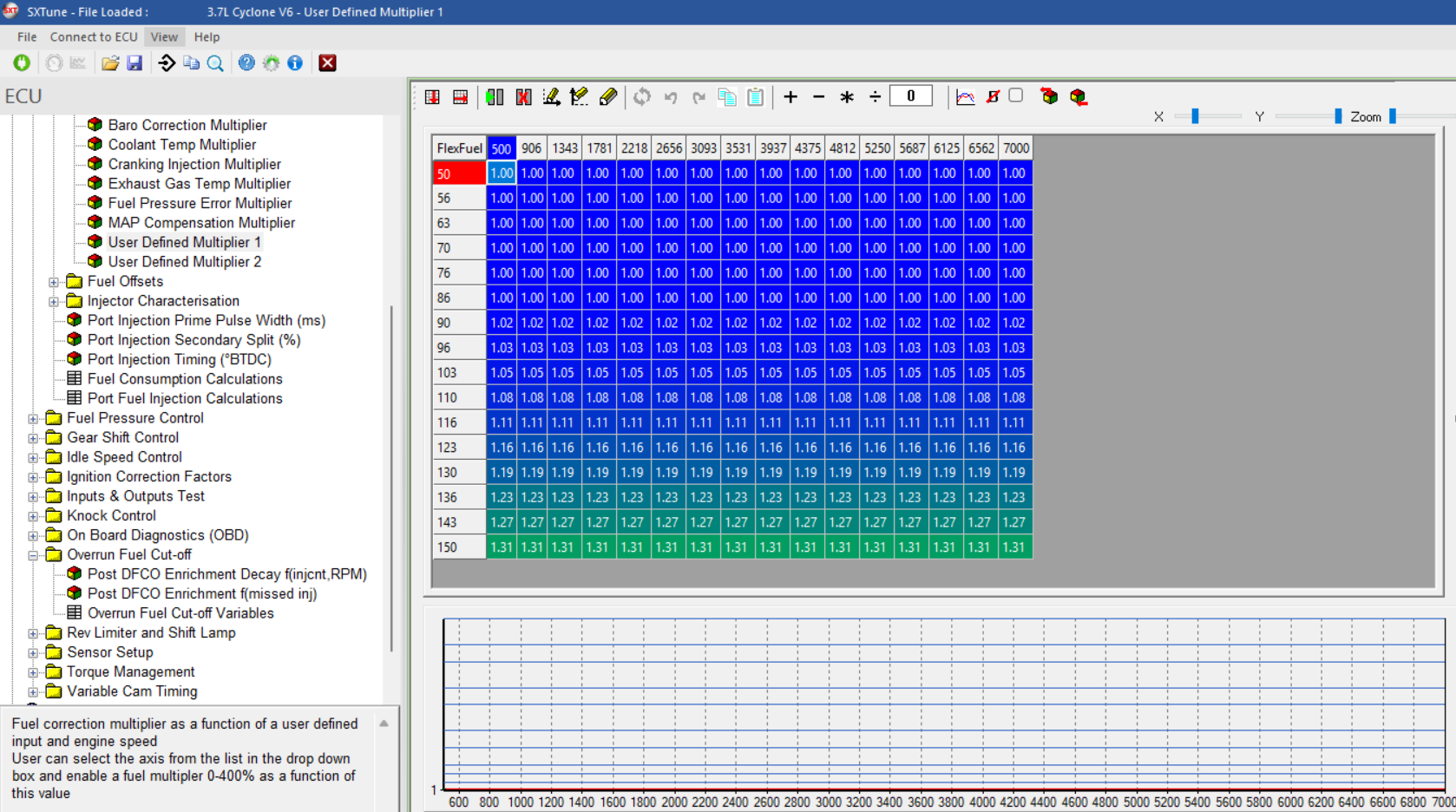
Image: an example of the user defined enrichment map for flex fuel correction
NB for flexfuel use additional fuel multipliers need to be configured to correct the cranking and afterstart fueling as well. This functionality is not used on the V6 turbo.
In a next step, the desired fuel injection pulse width is corrected with a number of additional offsets;
The battery voltage depending delay time for opening the injectors, a idle offset correction which is only used on older type engines with a separate idle air bypass valve on systems running on alpha/ N as a load signal and the offset from the transient fuel function for AE Acceleration Enrichment and DE deceleration enleanment.
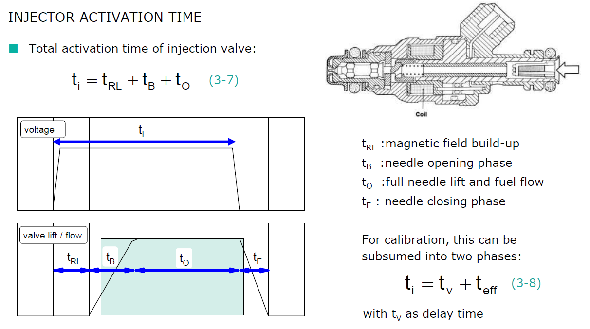
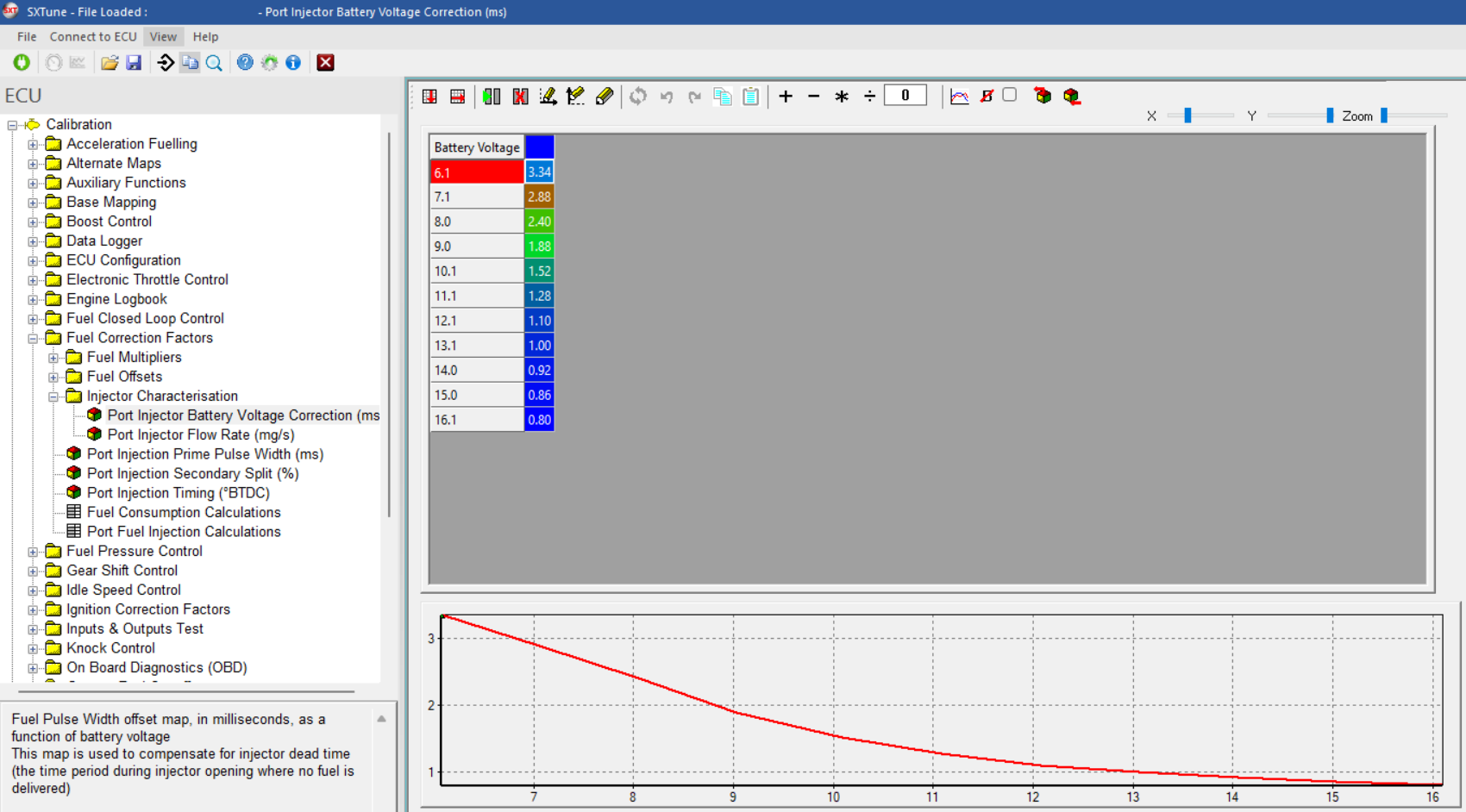
Image: an example of injector delay compensation map depending on battery voltage
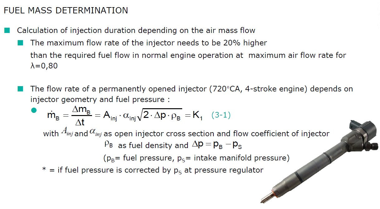
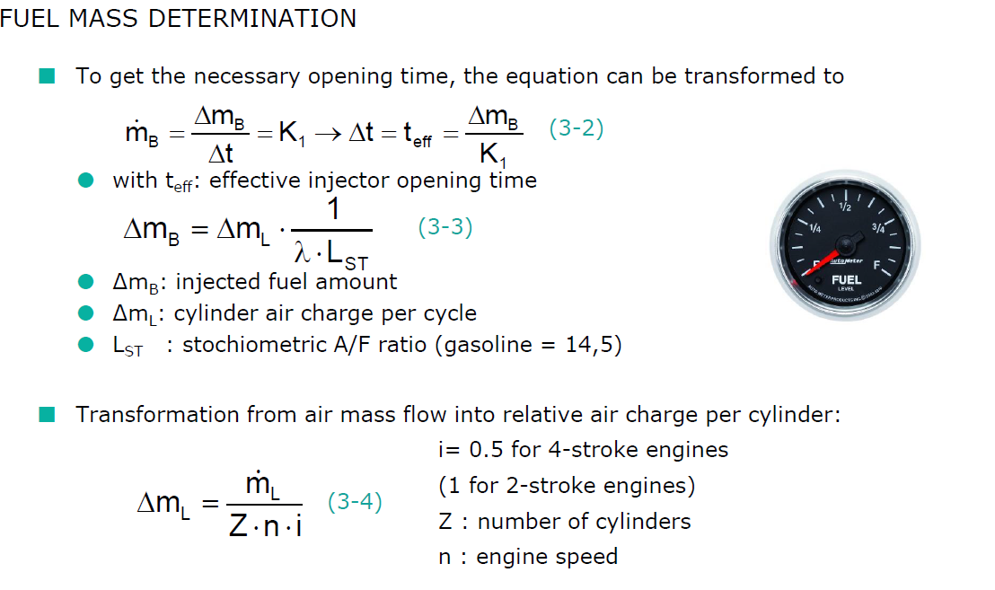
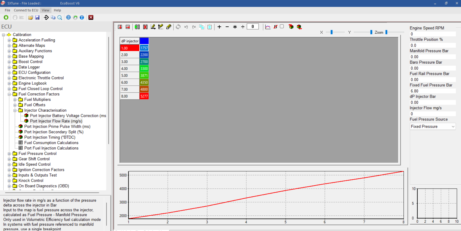
Image: an example of an injector flow characteristic calibration for a PFI injector
The injector flow characteristic is depending on the pressure drop over the injectors. On a PFI engine, it sees the intake manifold pressure MAP on one side and the fuel pressure on the other side. The fuel pressure can be read in as a variable from the sensor, or from a fixed calibrated value. This information is available from the injector supplier or can be found out by flowing the injectors on a testbench. The unit needed here is mg of injected fuel per second.
After all of these open loop corrections, we still need to add all of the closed loop correction factors to get towards the final injection pulse width.