
ECU Setup
Electronic throttle control (ETC)
Commission electronic throttle only after PPS and TPS scaling have been verified.
Recommended order
- Verify wiring and ECU configuration for the throttle body.
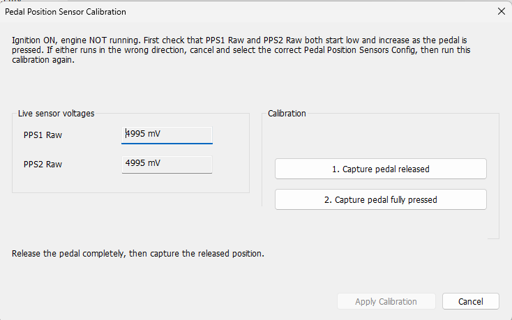
- Calibrate PPS.
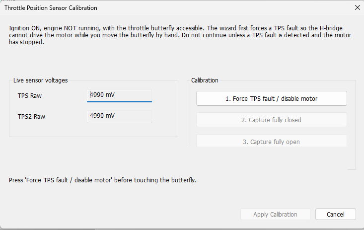
- Calibrate both TPS channels with the motor safely disabled during manual butterfly movement.
- Confirm the two TPS channels agree throughout travel and that diagnostic thresholds are appropriate.
- Restore normal motor operation and verify commanded throttle movement with the engine stopped.
- Only then proceed to target, feed-forward and closed-loop ETC calibration.
Delta 700: ETC Negative Slope Factor · ETC Negative Slope f(dTPSReq) % · ETC Positive Slope Factor
Delta 800: ETC Negative Slope Factor · ETC Negative Slope f(dTPSReq) % · ETC Positive Slope Factor
Delta 880: ETC Negative Slope Factor · ETC Negative Slope f(dTPSReq) % · ETC Positive Slope Factor
Delta 900: ETC Negative Slope Factor · ETC Negative Slope f(dTPSReq) % · ETC Positive Slope Factor
Delta GDI6: ETC Negative Slope Factor · ETC Negative Slope f(dTPSReq) % · ETC Positive Slope Factor
TPS calibration and validation
Procedure
- Connect SXTune with ignition on and engine stopped. PPS should normally be calibrated first.
- Disable throttle motor drive using the ECU's TPS-fault setup procedure before manually moving the butterfly.
- Select the correct electronic-throttle/throttle-body configuration.
- Select TPS sensor directions so both raw TPS signals increase as the throttle is opened.
- Move the butterfly fully closed and enter the two raw voltages as TPS minimum values.
- Move it fully open and enter the two raw voltages as TPS maximum values.
- Verify both scaled TPS channels travel from approximately 0% to 100% and track each other closely.
- Save, cycle ignition, confirm faults clear, then operate the pedal and check normal throttle operation.
Delta 400: Alt Target Throttle Position Scaler (%)
Delta 700: Alt Target Throttle Position (%) · Alt Target Throttle Position Scaler (%)
Delta 800: Alt Target Throttle Position (%) · Alt Target Throttle Position Scaler (%)
Delta 880: Alt Target Throttle Position (%) · Alt Target Throttle Position Scaler (%)
Delta 900: Alt Target Throttle Position (%) · Alt Target Throttle Position Scaler (%)
Delta GDI6: Alt Target Throttle Position (%) · Alt Target Throttle Position Scaler (%)
Safety and validation
Carry out calibration with the engine stopped. Before manually moving the butterfly, make sure the throttle motor drive is disabled so the H-bridge cannot move the throttle unexpectedly. The wizard starts by disabling motor drive before asking for the fully closed and fully open positions. After applying the calibration, cycle ignition as required and verify both TPS channels track together through the full range without fault flags.
Electronic throttle control strategy
The electronic throttle control or drive by wire system needs to be configured and set up first by choosing the correct options in the overview menu.
Here you need to choose the type of DBW throttles, the direction and type of position feedback signals as well as the same parameters for the pedal.
The following procedure should be followed exactly in the order shown.
1. Make sure the ignition is still in the on position (but the vehicle is not running). Open the Engine Calibration menu, then the Electronic Throttle Control submenu and finally open the Electronic Throttle Control Variables pane.
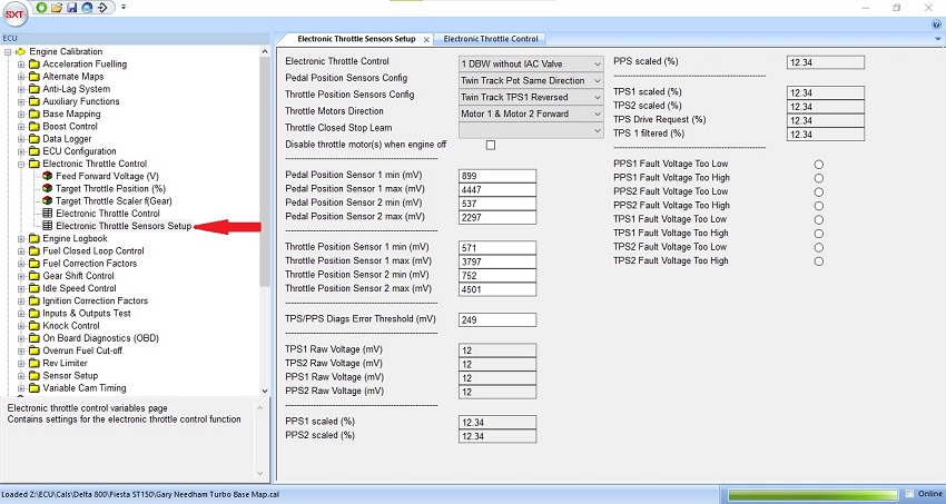
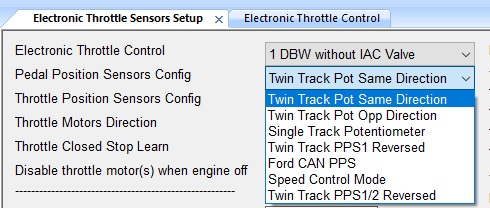
The two signals from the PPS can be observed in the PPS1 and PPS2 Raw Voltage (mV) field (they cannot be edited, only white fields may be edited). Firstly, check that both ‘PPS1 Raw Voltage’ and ‘PPS2 Raw Voltage’ start at a low value and increase when you press the pedal. If they do not, choose one of the options in Pedal Position Sensors Config until they both operate in the correct direction.
We will first calibrate the signal from the PPS1 sensor channel. Without
touching the pedal, observe the voltage in the PPS1 Raw Voltage field
(as indicated by arrow 1 in the image below). This value should be
increased by 50 before being entered into the field Pedal Position
Sensor 1 min (arrow 2). Increasing the value by 50 will allow a very
small initial pedal travel before registering throttle demand.
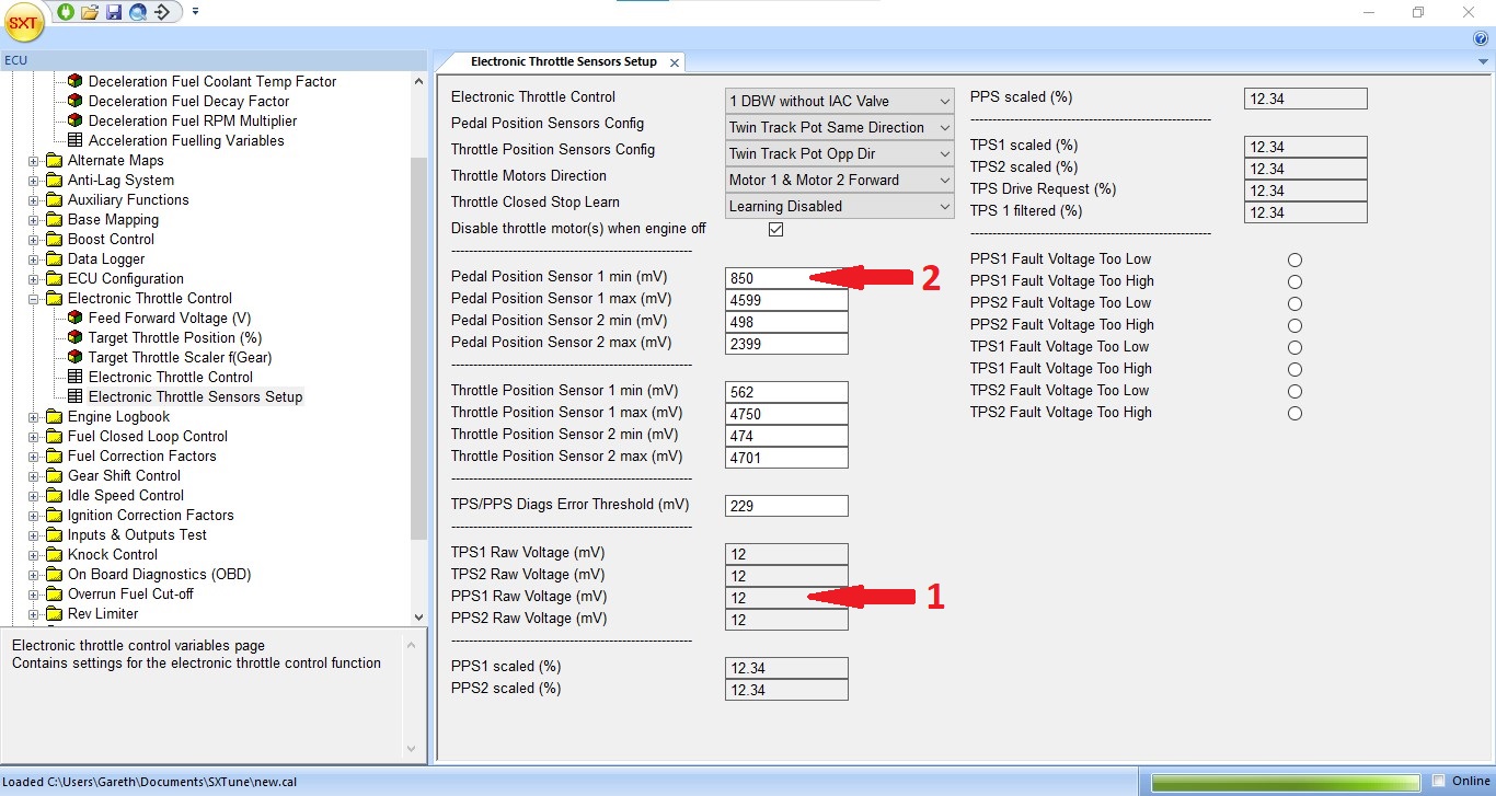
Image: the E pedal setting for min and max limit definition
3. Now the throttle must be fully depressed. It is important to press the pedal as hard as possible (as you would in racing conditions) to ensure the pedal is pushed down as far as it will go. Observe the new value in the field PPS1 Raw Voltage (arrow 3). Subtract 50 from the value and enter the result into the Pedal Position Sensor 1 max field (arrow 4). Reducing the value by 50 will ensure that maximum throttle demand is detected just before the pedal is fully depressed.
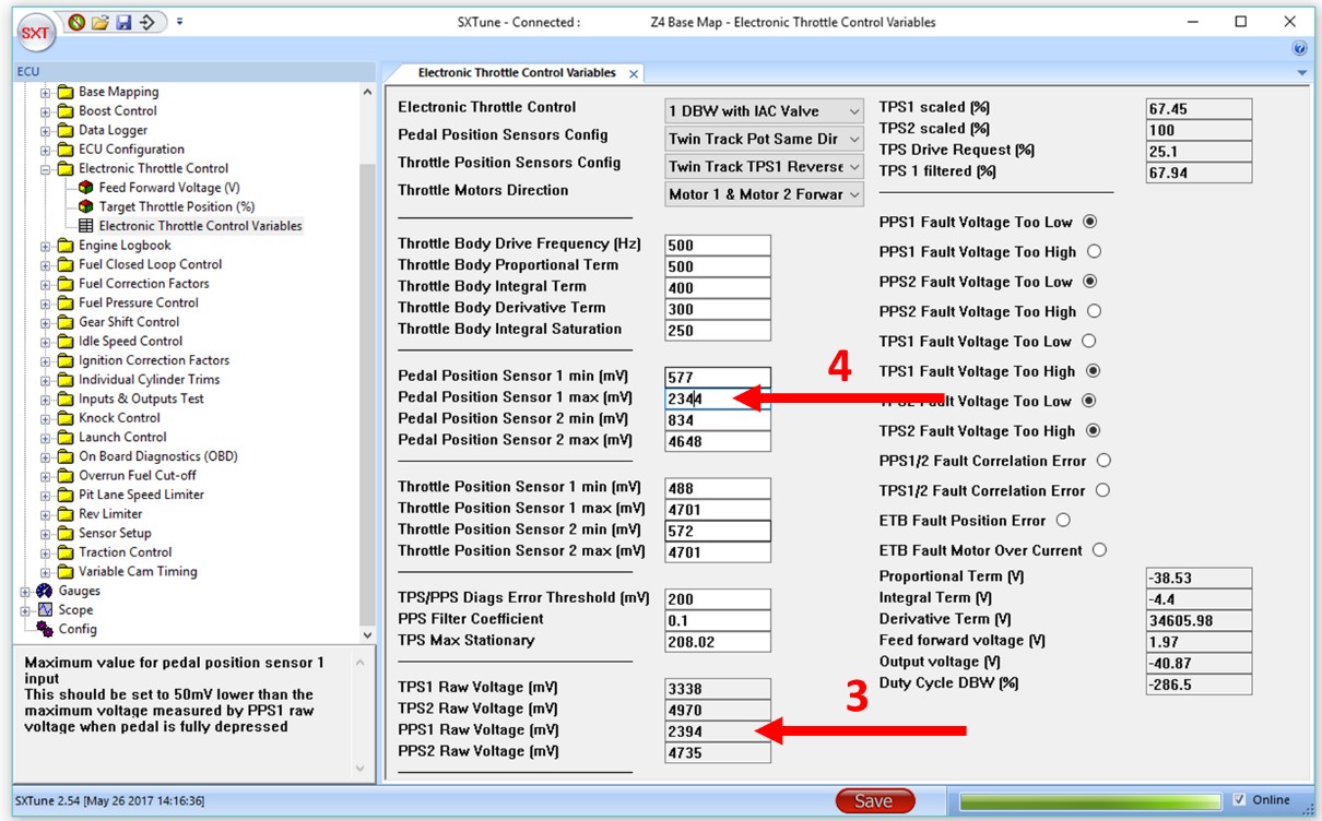
Image: the Egas overview table
4. You should now follow the same procedure for both max and min values for the PPS2 sensor. Make sure you observe the value in PPS2 raw voltage (not PPS1 Raw Voltage) and fill in the value adding and subtracting 50 as before, but in the PPS2 fields. When complete, click Save to copy the values to the ECU (arrow 5). The save button should change colour from red to green. Turn the ignition switch off for 2 seconds and then turn it back on again. This will clear the stored faults (PPS voltages Too High/Low) which will have been logged as the PPS was being calibrated. The radio buttons should now be showing clear (arrow 6) where before some were set (you can see this in the diagrams above).
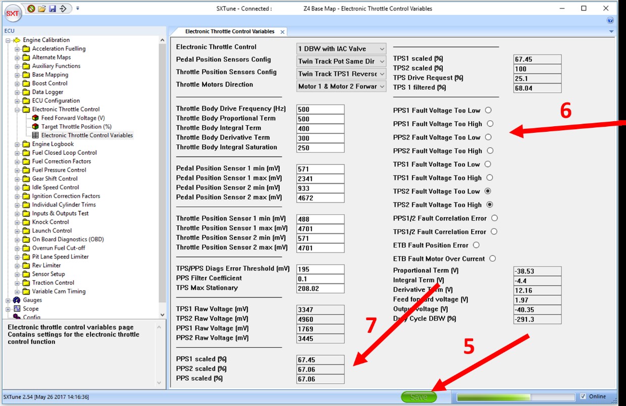
Image: the E pedal settings
Check the Calibration
Operate the pedal over its full range and check that it changes from 0% to 100% for both PPS1, PPS2 and PPS (arrow 7) at the bottom of the SXT pane. The values may not be exactly the same but they should be quite close. Both must show 100% when the pedal is fully depressed and 0% when the pedal is not depressed. It should be possible to touch the pedal very lightly before pedal displacement is registered (this is due to the 50 mv added step 6). Similarly 100% throttle should be observed just slightly before the pedal is fully depressed.
TPS (Electronic Throttle)
Overview of Process
The electronically operated throttle body requires configuration with the butterfly valve exposed so that the valve can be changed from its resting position (limp home position set by a spring in cases where no IAC valve is used) to completely closed and then completely open. In these two states the voltage ranges produced by the body are read and entered into the ECU via SXTune. It is best to first have configured the PPS sensor as described above.
Configuring the TPS
Make sure the ignition is in the on position (but the vehicle is not running). Open SXTune and connect to the ECU.
Open the Engine Calibration menu, then the Electronic Throttle Control group and double click the Electronic Throttle Control Variables option.
1. First, temporarily set the Throttle Position Sensor 1 max(mv) value to 0 in order to generate a TPS fault. Click into any another box after entering the 0 (you will overwrite this value in step 5). Check that there is a TPS fault set in any one of the four TPS Fault Voltage Too High/Low indicators at the bottom right of the window. With a fault indicator set, the H-Bridge motor will no longer drive the valve (there should be no whirring sound from the throttle body anymore) and you will not risk trapping a finger when manually moving the butterfly during the rest of the setting up procedure.
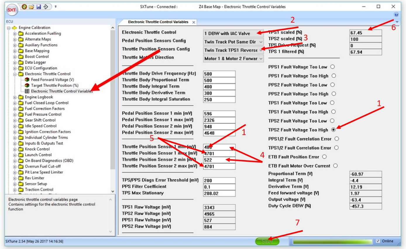
Image: the throttle and pedal min and max limits to be calibrated.
2. Configure the type of throttle body in Electronic Throttle Control. For example 1 DBW with IAC Valve would be chosen for a single throttle body with a seperate IAC Valve.
3. Choose the correct potentiometer directions in Throttle Position Sensors Config. This can be found by pushing the valve open and observing that the voltages in TPS1 Raw Voltage and TPS2 Raw Voltage both increase as the valve opens. If they don't, try the other options until they do.
4. Push the valve completely closed and note the TPS1 Raw Voltage and TPS2 Raw Voltage values. Enter these values into the Throttle Position Sensor 1 min(mv) and Throttle Position Sensor 2 min(mv) fields.
5. Now press the butterfly fully open, making sure it is at its maximum travel and cannot be opened any further. Again, note the TPS1 Raw Voltage and TPS2 Raw Voltage values. Enter these values into the Throttle Position Sensor 1 max(mv) and Throttle Position Sensor 2 max (mv) fields
6. Push the butterfly open and closed checking that the values in TPS1 scaled (%) and TPS2 scaled (%) move between to 0 and 100 and that the two values are with a few percent of each other as they change. Set the TPS/PPS Diags Error Threshold (mv) field to 249 if it is not already this value.
7. Press the save button at the bottom of the window, changing it from red to green. Turn off the ignition for a couple of seconds and turn it back on again. The TPS fault indicators should be clear. Operate the pedal and check the butterfly opens and closes without triggering any fault indicators.
In a next step the min and max values for both throttle and pedal position sensors need to be calibrated correctly to avoid errors.
An error is set as soon as one of the position feedback signals goes outside of the calibrated min/ max ranges with more that the TPS/PPS Diags error threshold.
The error will immediately stop the throttle control and make it de-energised. The errors can only be reset by recycling the ignition key.
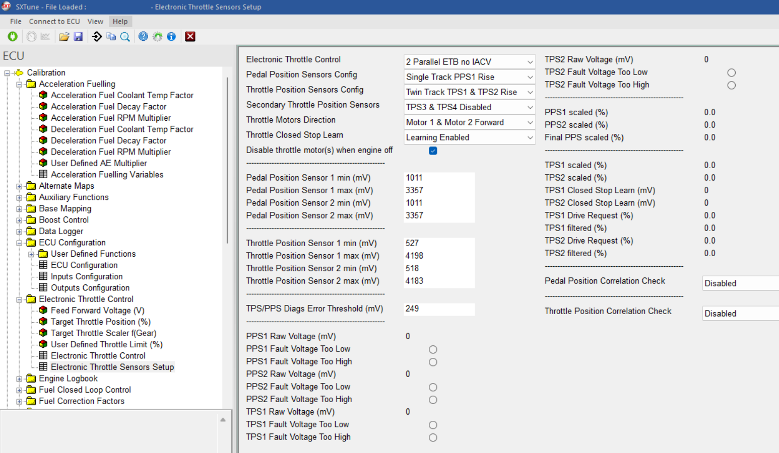
Image: the Egas overview table
The target throttle map defines the relation between the pedal angle and the desired throttle angle for each engine speed. This should be calibrated to taste but it is very important here to create a very smooth map as everything else will immediately lead to driveability issues.
You need to make sure that when the driver goes through the engine speed with a constant pedal value, he does not get unexpected levels of acceleration.
A second alternative target throttle map can be created under alternate maps. Here you could for example create a more sporty map which can then be selected over a sports mode switch in the vehicle.
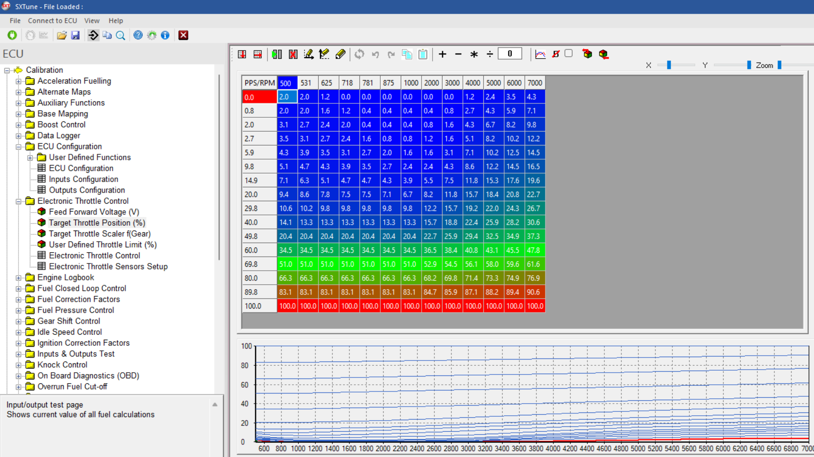
Image: the Egas target throttle map
The target throttle map it`s output gets multiplied with a gear dependent factor. In this way we can create a more sensitive behaviour in the lower gears for more doseability and a steeper more responsive behaviour in the higher gears.
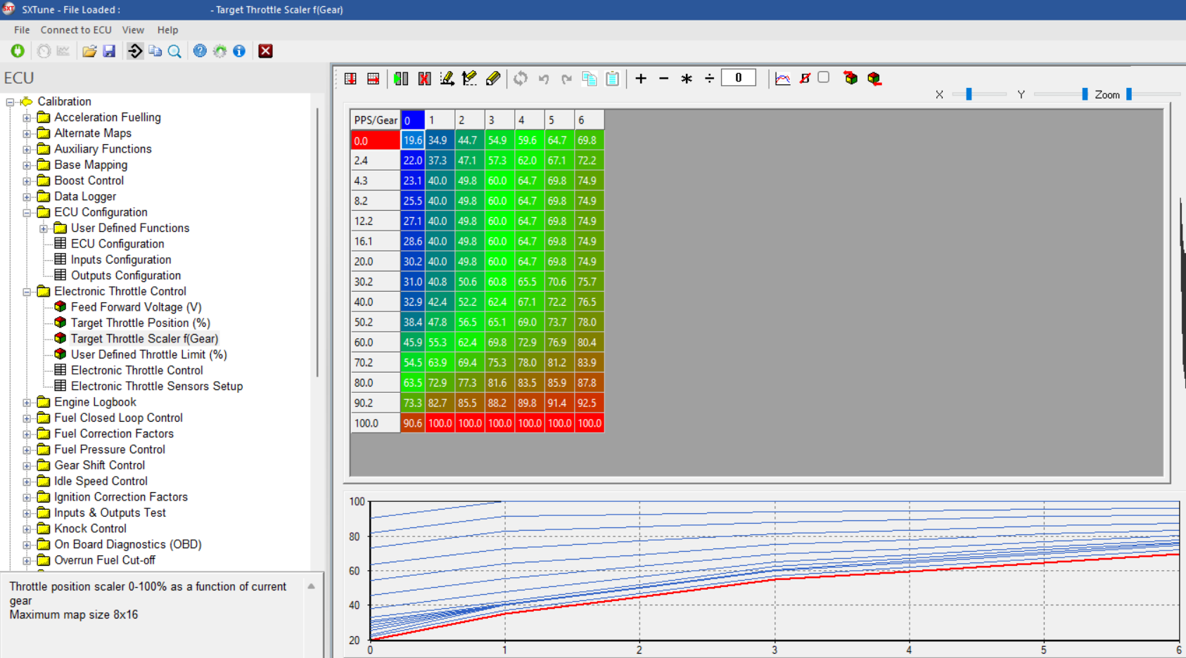
Image: an example for the gear dependent target throttle multiplier map
With the user defined throttle limitation function, one can make all kind of random throttle limitations depending on critical temperatures or max. vehicle speed limites or also for example when the CAN communication with an other system breaks down.
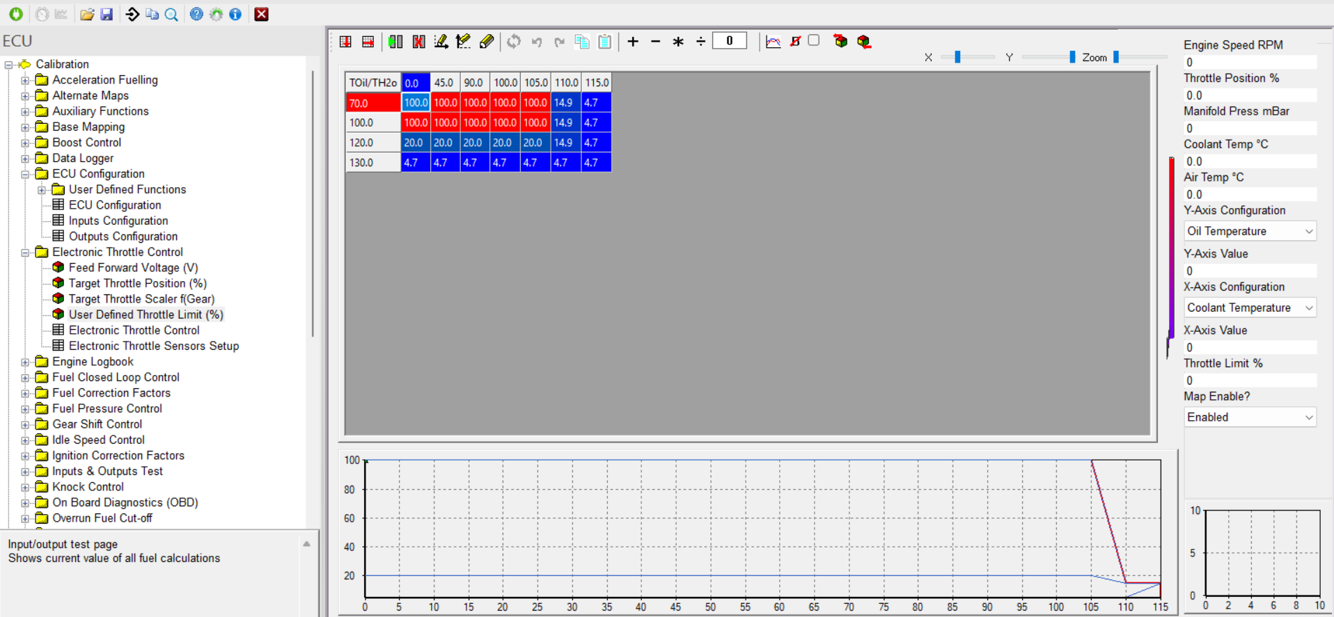
Image: an example for a user defined throttle limitation.
E- Gas safety
To avoid any risk of undesired acceleration, all of the sensors are made redundant by making all outputs double.
The ecu can monitor the difference between the different tracks of both the pedal and the throttle and make a correlation. If the difference between the two, goes over a calibrateable threshold for a time longer than the bounce threshold (target TPS error time), an error will be set and the throttle control will be switched of, leaving the engine in idle.
The same methodology is also used between the target throttle and the actual position. Also here we can trigger an error which either activates a max engine speed (controlled over fuel cut) or switches of the throttle control making the throttle close so that only idle operation is possible.
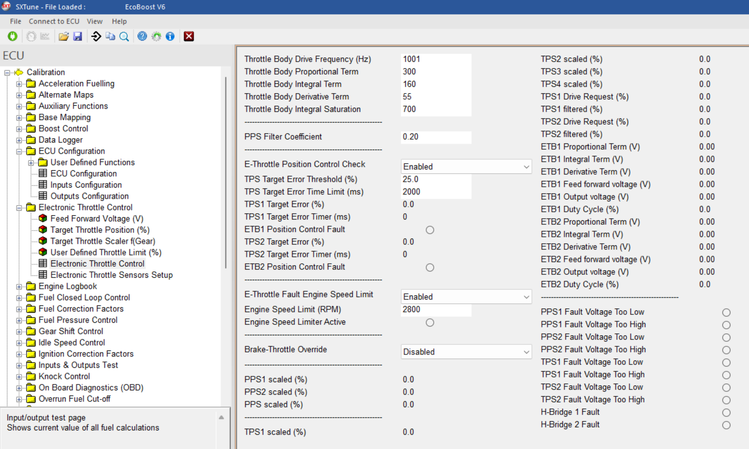
Image: throttle safety functions overview
We also have a brake override function which will always have
priority over any throttle command, either from the driver or any other
system in the vehicle (transmission, hybrid controller, cruise control).
If the brake is pressed at the same time as the throttle for a given
time, it will limit the throttle control returning the engine back to
idle and thus avoiding any unwanted acceleration.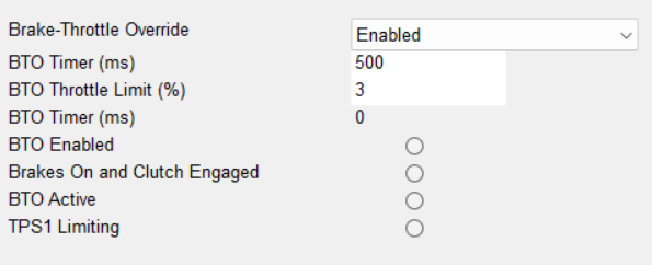
Image: brake throttle override limitation