
Calibration & Control
Variable cam timing (VCT)
Set cam-position measurement correctly before tuning closed-loop cam target control.
Measurement first
The VCT variables include cam-position offsets for up to four measured cams. These offsets establish the zero/reference relationship; closed-loop target tuning should not be used to compensate for an incorrect measured cam position.
Control
Variable cam timing settings include control-valve frequency, target-angle rate limiting, proportional and integral gains, and target inlet/exhaust cam-angle maps where supported. Some applications also provide cam-profile switching thresholds.
Recommended order
- Verify crank/cam synchronisation.
- Verify measured cam angle and set offsets.
- Confirm the control valve moves the cam in the expected direction.
- Set conservative target maps.
- Tune closed-loop gains only after mechanical response is known.
Variable valve timing control strategy
The variable valve control function can control up to 4 VVT systems on an engine.
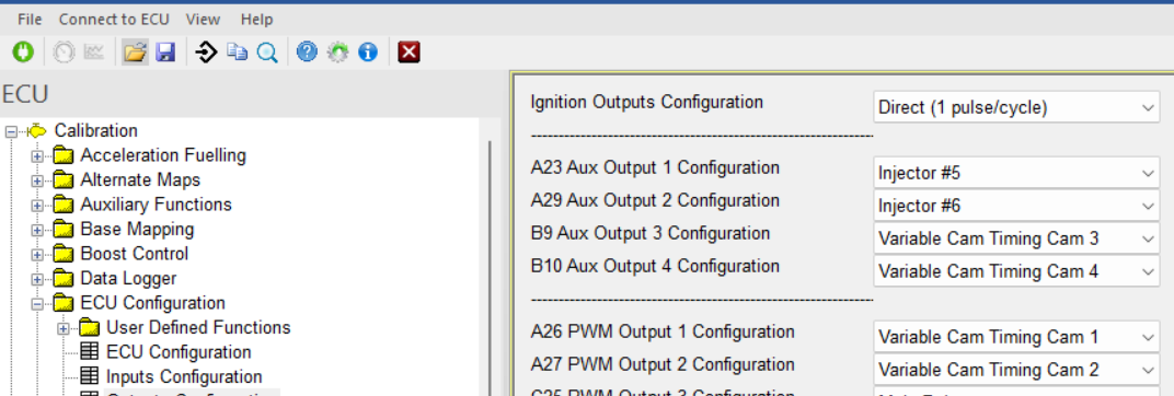
Image: outputs configuration for VVT
They need to be configured correctly under ECU config, output configuration and their feedback signals need to be configured correctly under inputs configuration.
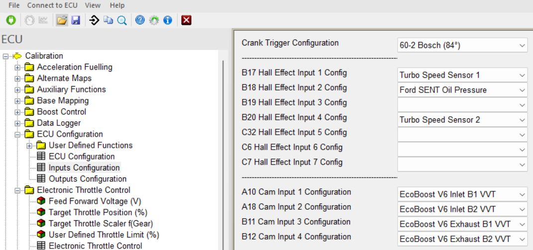
Image: inputs configuration for VVT
Under inputs configuration, the correct cam trigger pattern has to be chosen. Either it is already preconfigured in the firmware such as for the ecoboost V6 in the example above, or it still needs to be defined.
To define a user defined cam trigger pattern for VVT the following steps need to be performed:
Pick a user defined VVT profile under inputs configuration:
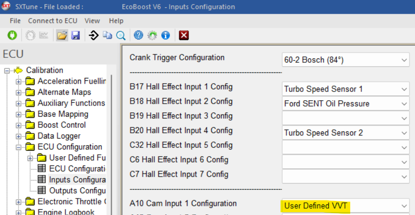
Image: user defined VVT trigger pattern
When the engine is running in idle go to the VVT cam trigger capture page:
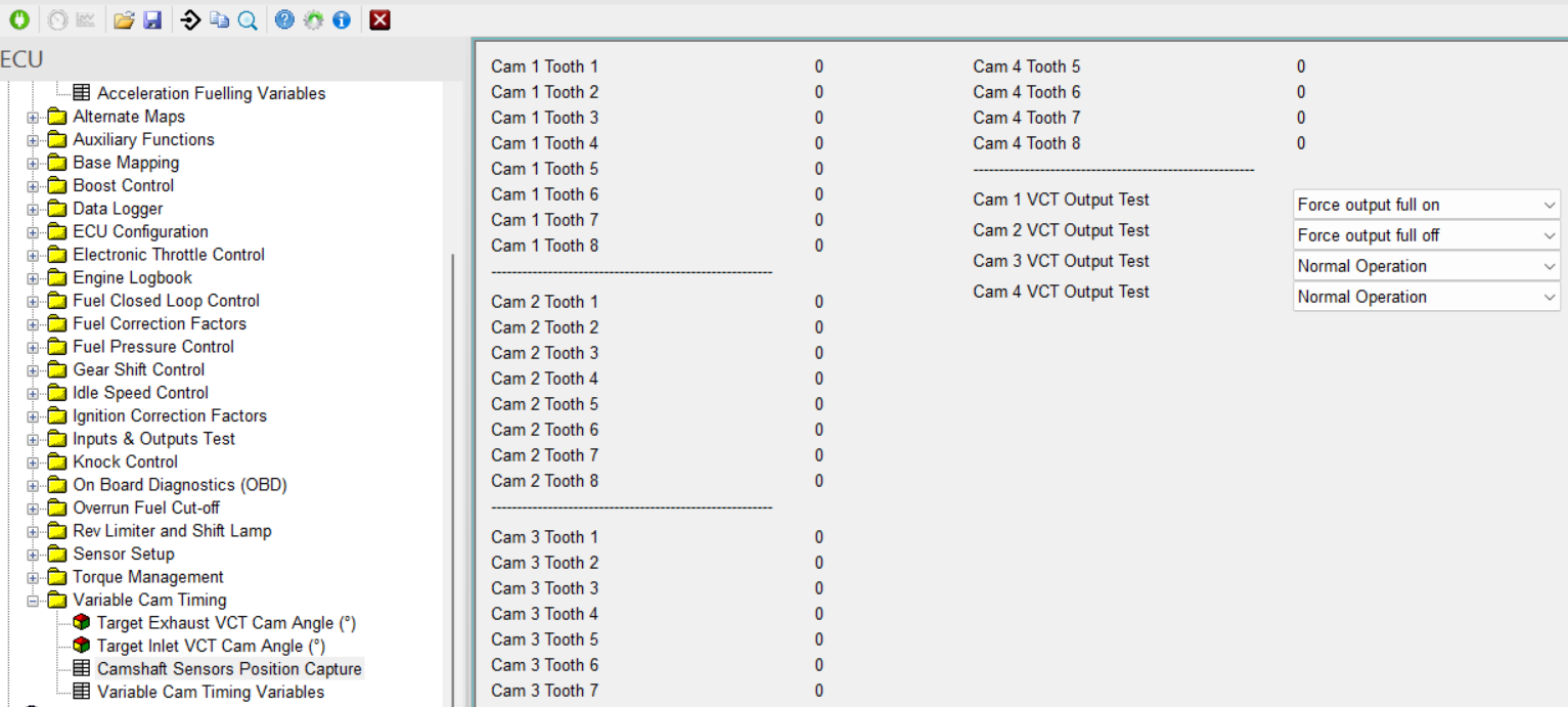
With the options force output off and on, you can push the VVTs to their extreme positions one after the other. For each position note down all the different values you see at cam 1 toot 1 to 8. You can then eliminate all values which are repeating themselves. Do this once for the full off position and then once for the full on position.
With these values the cam trigger pattern can be defined on the page of the next image. For open crank tooth number you write the lowest value found above, for close the highest value for the same tooth nr. The difference between the two, multiplied with the number of crank degrees per crank trigger tooth will give you the range of the VVT phasers in degrees of crank angle.
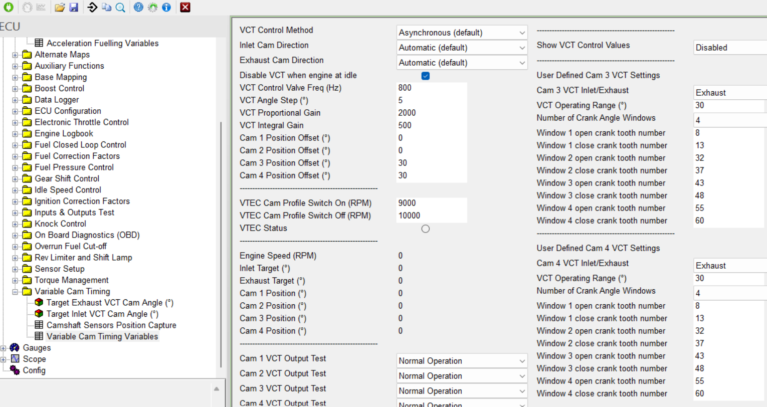
Image: user defined VVT trigger pattern definition example
Once these trigger definitions are configured correctly, the normal VVT operation mode can be activated.
The ECU will control the VVT position to the target by varying the PWM value to the cam actuactor.
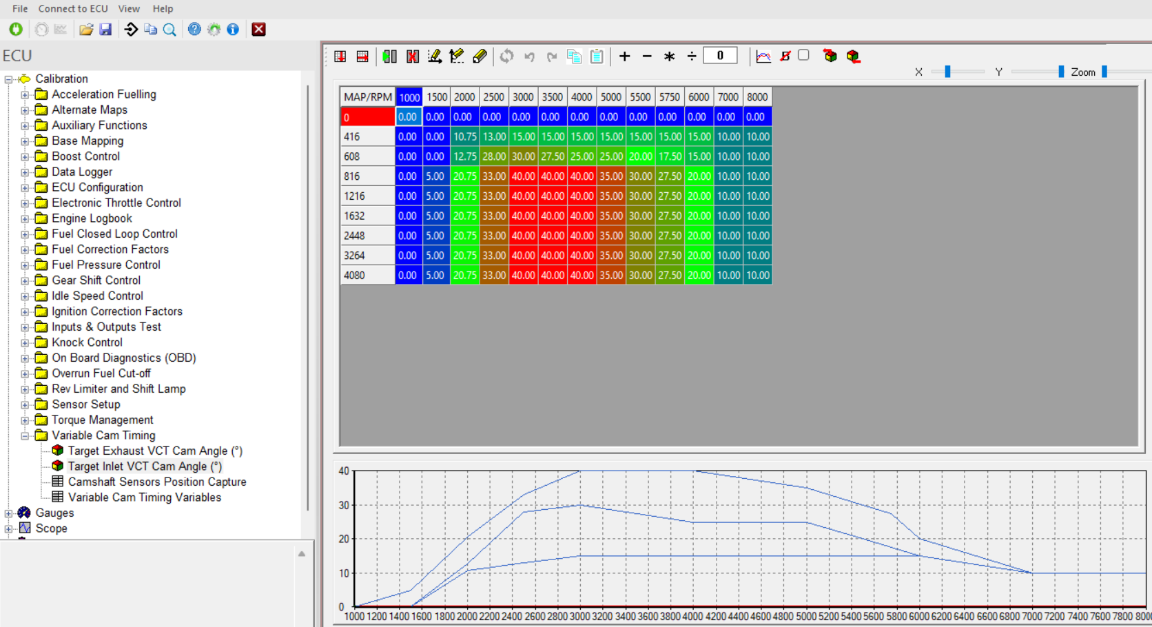
Image: target intake vvt map example
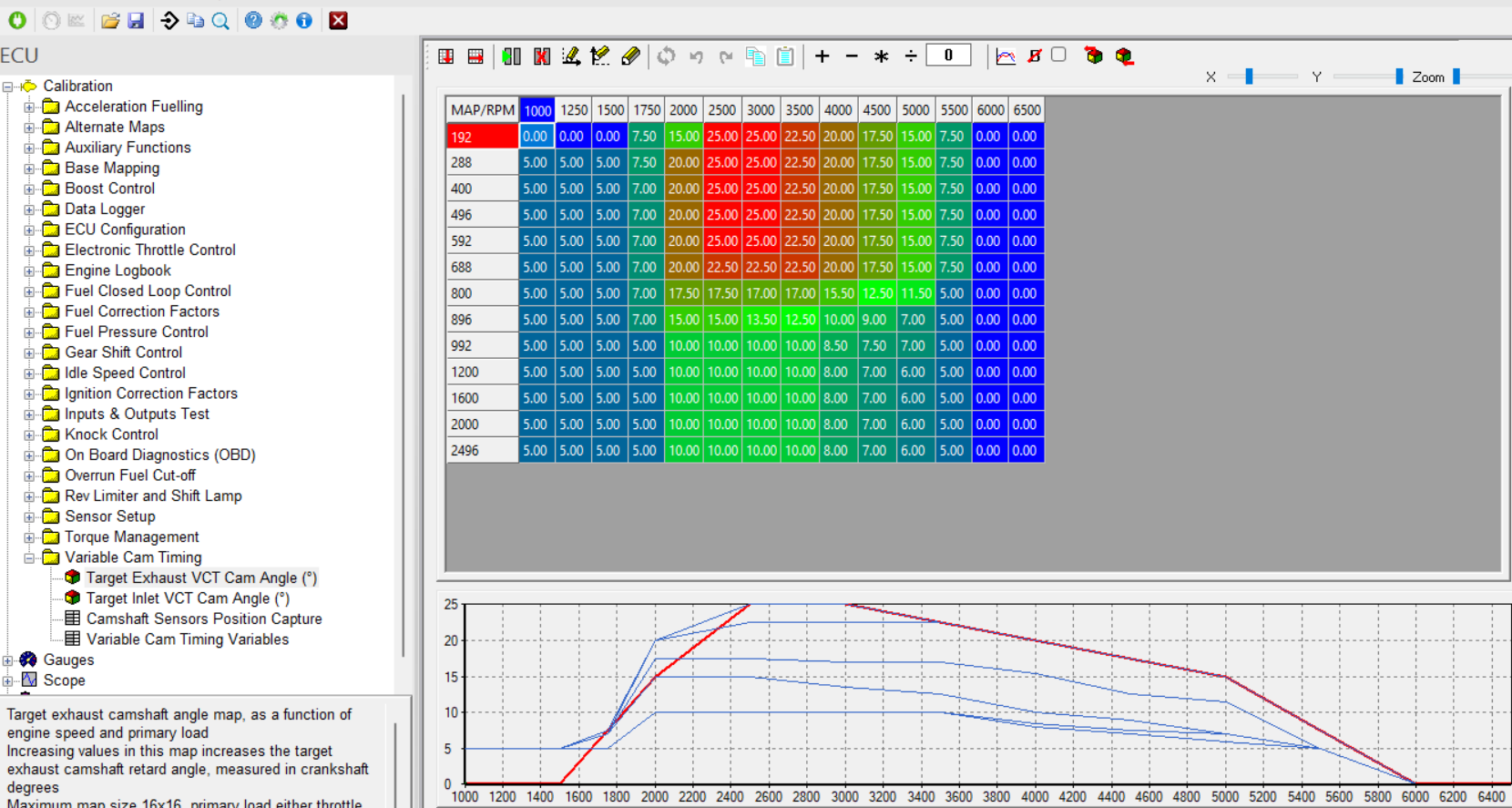
Image: target exhaust vvt map example
The optimal vvt positions need to be calibrated looking at the following criteria: optimal performance, optimal fuel efficiency, minimal engine out raw emissions for Nox. It is important to keep the maps smooth here.
Typically the engine like more valve overlap at low engine speeds and less the higher up you go in engine speed.
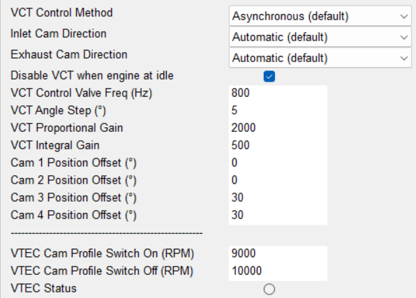
Image: vvt control parameters overview
The optimal setting for the vvt controller are the ones that give you a quick response putting the acutal position on to the target position without creating any big overshoots or oscillations.