Calibration & Control
Delta 900 centre differential control
Configure the hydraulic inputs/outputs, mode switch, accumulator pump and acceleration/braking clutch maps.
1. Configure inputs
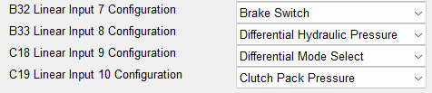
In ECU Configuration → Inputs Configuration, assign the Brake Switch, Differential Mode Select Switch, Differential Hydraulic Pressure and Clutch Pack Pressure inputs.
2. Configure outputs
In Outputs Configuration, select the CDC Valve (B3) and Accumulator Pump (B4) outputs. Configure ACD status-light outputs if required.


3. Calibrate pressure sensors
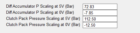
In Sensor Setup → Analogue Inputs Setup, enter the 0 V and 5 V calibration values for the accumulator/differential hydraulic pressure and clutch-pack pressure sensors.
4. Mode switch and pump thresholds
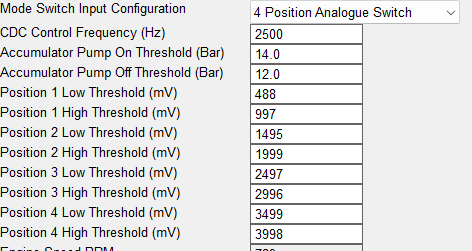
In Centre Differential Control Variables, choose the Mode Switch Input Configuration and calibrate the voltage ranges for the required positions. Set the accumulator pump On and Off pressure thresholds.

5. Brake switch
Check that the brake status illuminates with the brake pressed. If the logic is reversed, use Invert Brake Switch Input.

6. Calibrate the mode maps
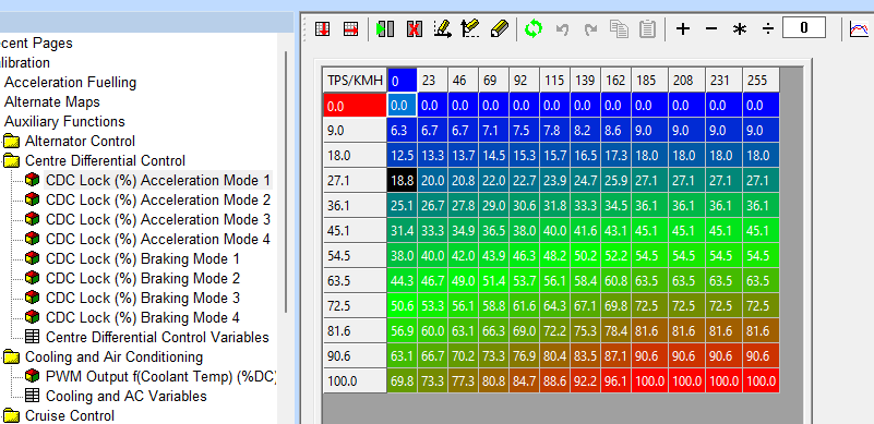
Populate all four acceleration and all four braking maps with the required clutch duty cycle as a function of vehicle speed and throttle position.