
Calibration & Control
Knock control setup
Configure the knock-control limits, detection window, signal gain, threshold, cylinder assignment, retard and recovery, then validate the system using the Knock Control Scope.
1. Knock Control Variables
Fill in the fields on the Knock Control Variables page as described below.
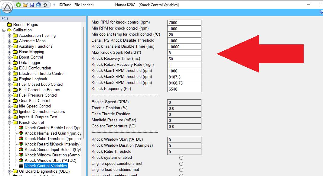
Max RPM for knock control
Knock control switches off above this engine speed. Set it at the rev limit, or at the engine speed where sensor noise becomes too high for knock control to operate reliably.
Min RPM for knock control
Knock control switches off below this engine speed. Set it at the lowest engine speed where knock can be reliably detected by the sensor; approximately 1500–2000 rpm as a typical region.
Min Coolant Temp for Knock Control
Knock control switches off below this coolant temperature. Race engines with larger-than-normal clearances can generate more mechanical noise when cold and are less likely to knock. Disable knock control until the engine is warm where necessary to avoid false detection.
Delta TPS Knock Disable
Normally disabled by setting it to 1000. If required, use this threshold to temporarily disable knock control on engines that generate false knock events during rapid throttle movement.
Knock Transient Disable Timer
Sets the time in milliseconds after the Delta TPS condition has been triggered before knock control is re-enabled.
Max Knock Spark Retard
Sets the total limit for knock ignition retard for each cylinder. A typical range is 4–8° as a typical range.
Knock Recovery Timer
After a knock event, the applied knock retard is held for this time before recovery begins.
Knock Retard Recovery Rate
Sets the rate at which ignition timing is ramped back towards the mapped value after the Knock Recovery Timer expires, in degrees of spark advance per ignition event.
Knock Gain1/2/3 RPM Threshold
These are hardware gain-level thresholds. Leave them at G1 = 1000 rpm, G2 = 8000 rpm and G3 = 8500 rpm unless advised otherwise by SCS.
Knock Frequency
The knock frequency is defined by the engine bore size. Determine the appropriate frequency for the engine before carrying out the signal-gain calibration.
2. Knock Control Enable Load
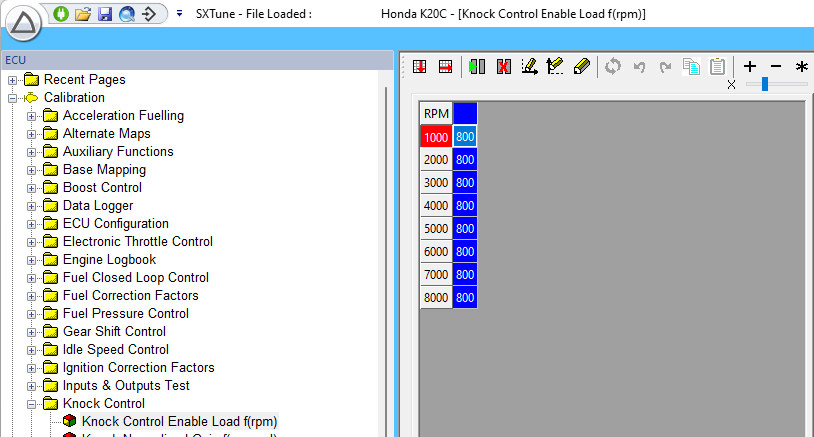
This map sets the engine load point above which knock control is enabled. It uses the configured primary load value, either MAP or TPS, as a function of engine speed. Set the threshold where knock detection is required and where it can be measured reliably. Typical starting regions are approximately 800 mBar MAP or 60% TPS.
3. Knock Normalised Gain
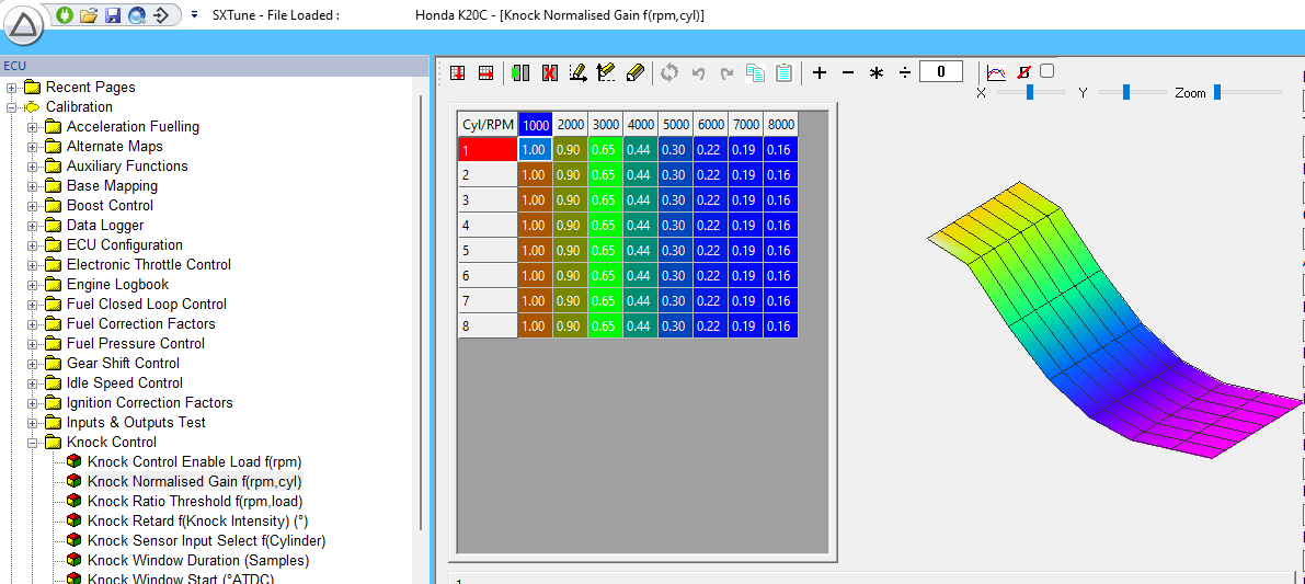
The Knock Normalised Gain map multiplies the Knock Ratio signal to scale it to the required level. Adjust this map in real time, preferably on a dynamometer, so that the Knock Ratio for each cylinder is just below the Knock Ratio Threshold at each engine-speed breakpoint when the engine is not knocking.
4. Knock Ratio Threshold
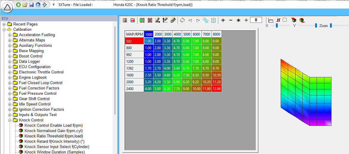
If the Knock Ratio for a cylinder rises above the Knock Ratio Threshold, the ECU considers that cylinder to be knocking. When knock control is enabled, an ignition correction is then applied to that cylinder's final spark advance.
Set the threshold in real time, preferably on a dynamometer, so that it is above the normal non-knocking Knock Ratio at each speed and load breakpoint. Leave approximately a 1–2 ratio-unit margin between the normal Knock Ratio and the threshold.
After setting the map, temporarily increase the base spark advance to confirm that genuine knock causes the Knock Ratio to exceed the threshold and that the ECU successfully detects the event.
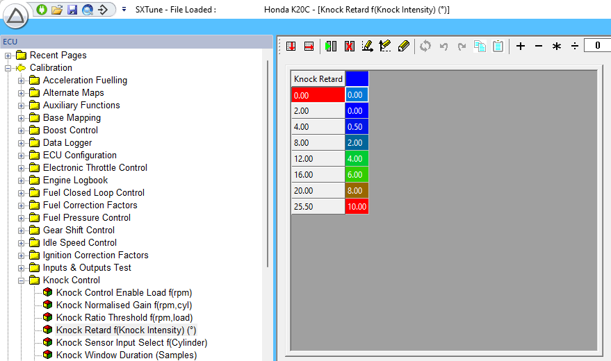
5. Knock Retard
Knock Intensity = Knock Ratio − Knock Threshold. The Knock Retard map uses this intensity to determine the ignition correction. This allows a small knock event to produce a small retard, while a larger event can produce a much greater correction. The values shown are examples and should be adjusted for the application.
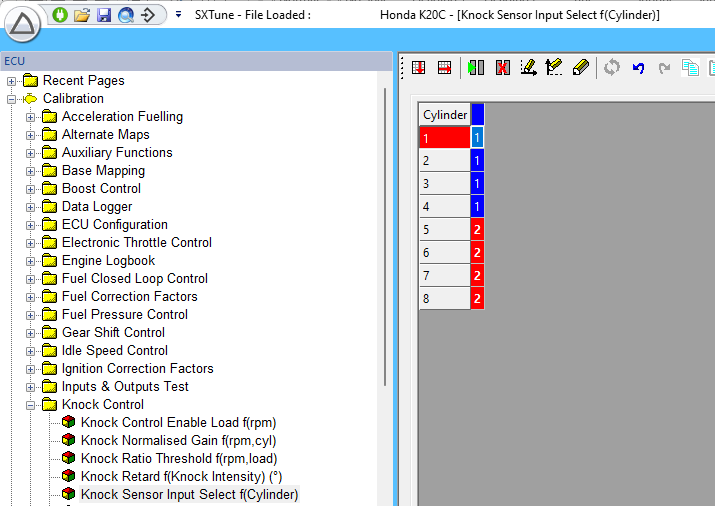
6. Knock Sensor Input Select
This map determines whether knock sensor input #1 or #2 is allocated to each cylinder.
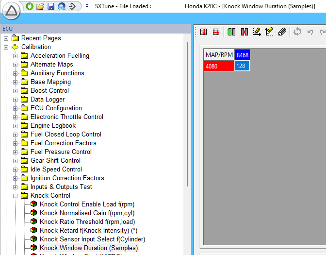
7. Knock Window Duration
Sets the number of samples used by the ECU's digital filter to calculate Knock Ratio. More samples cover a longer crank-angle duration and may capture more of the knock signal, but may also include more mechanical background noise. Typical values are 120–250 samples as typical values. Adjust the duration to achieve the best signal-to-noise ratio for the engine.
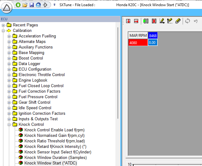
8. Knock Window Start
Sets the crank angle After Top Dead Centre (ATDC) at which the knock window opens for each cylinder. The guide notes that knock commonly occurs around 8–12° ATDC. The value can be mapped against engine speed and load if required. Set the start angle to maximise knock detection while avoiding unrelated mechanical noise such as valve-closing events.
9. Knock Control System Validation
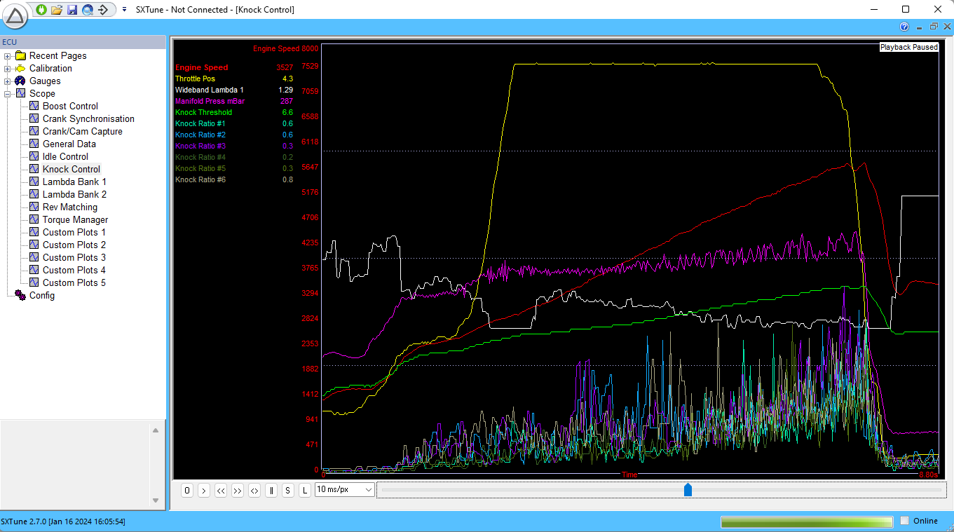
A correctly configured system should resemble a Knock Control Scope trace. When the engine is not knocking, the Knock Ratios for all cylinders at full load should be non-zero but remain below the Knock Threshold. During a knock event, the Knock Ratio for the affected cylinder or cylinders should rise above the threshold and the corresponding cylinder-specific ignition correction should be applied to stop the knock.
Knock detection and control principles
The knock detection on the SCS D900 ECU is based on a piezoelectric knock sensor which transforms vibrations inside the block into electrical noise signals with the same frequency.
Knock is self ignition of the mixture inside the combustion chamber. It can occur due to different reasons such as hot spots, too much residual gas in the cylinder or excessive pressure due to high compression or engine load.
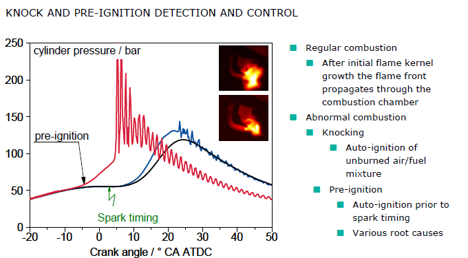
Image: knocking combustion cylinder pressure trace
The knock detection compares the noise integrated and rectified in a calibrated window just after firing tdc for the igniting cylinder and compares the noise level from a non knocking combustion with the noise level of a knocking combustion to detect the knock event.
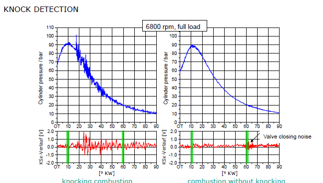
Image: knocking combustion cylinder pressure trace compared to a non knocking event.
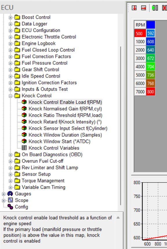
Image: knock detection enablement load level
Since knock only occurs at higher engine loads, the detection control is only enabled above a calibrateable load threshold. This is done to avoid false detection.
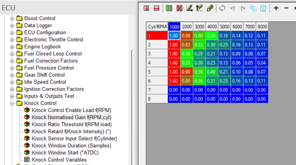
Image: knock detection gain
The knock sensor signal needs to be amplified to make the difference between knocking and non knocking combustion more clear. The level of correct amplification is dependent on the engine speed and the cylinder because the knocking noise will have a different transfer function through the engine block for these different conditions.
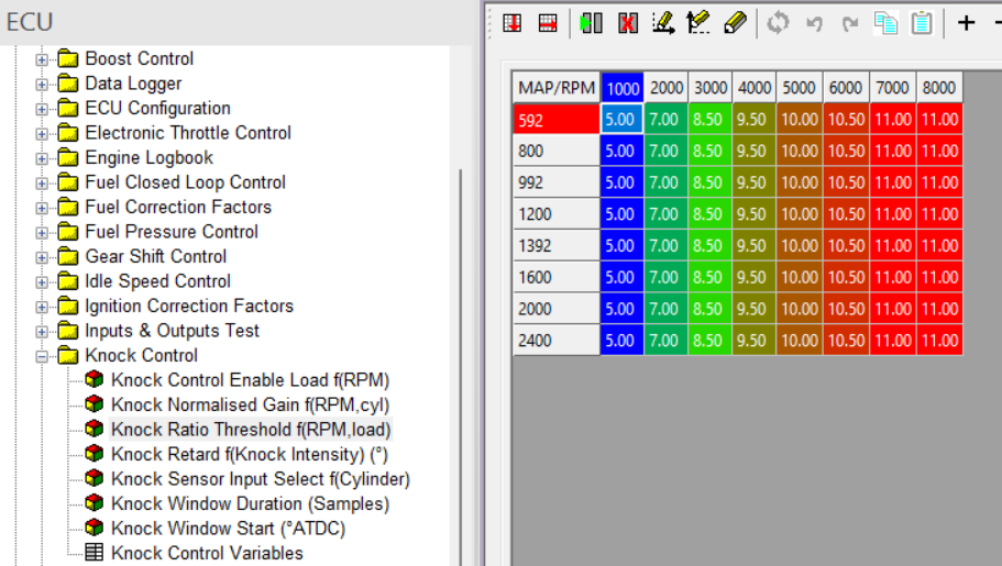
Image: knock detection threshold table as calibrated in the
The amplified knock sensor signal is compared to the detection threshold. The threshold is depending on the cylinder speed and load point. It needs to be calibrated to detect as much as possible the real knocking combustions and avoid false detection.
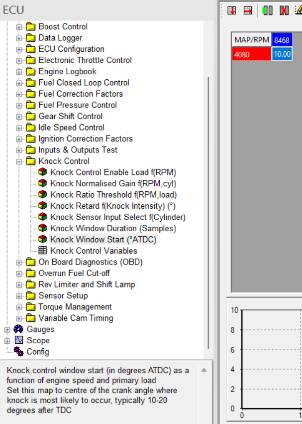
Image: the start value of knock detection window as calibrated in the
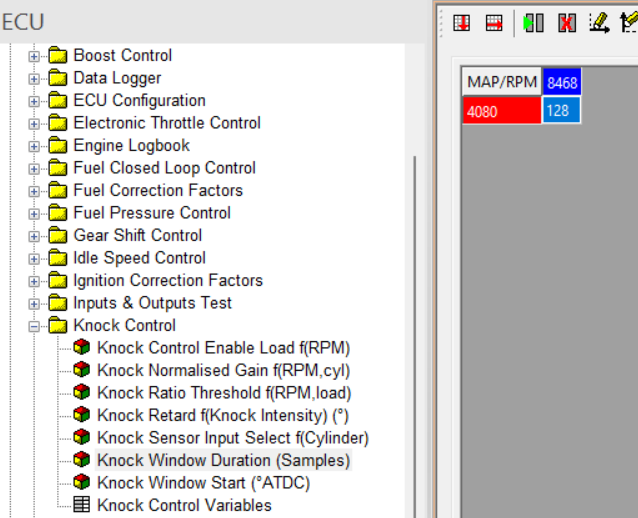
Image: the duration of the knock detection window as calibrated in the
To avoid false detection due to other mechanical noises such as valve closing, the detection window has to be as small as possible but still big enough to detect knock also in situations with a more retarded ignition angle window.
Depending on intensity of the how much the amplified knock noise goes over the threshold, the ecu will apply a stronger spark correction. This can be calibrated in the following map:
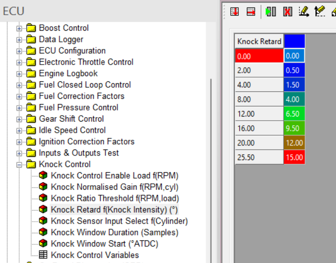
Image: the intensity of the knock correction as calibrated in the
Each detected knock event will lead to a new correction. If the following combustion events do not show knock levels over the threshold, the ignition angle will advance again towards the original value without knock correction with a speed depending on the calibrated knock recovery time.
The max. knock correction is limited to a fixed calibrateable value.
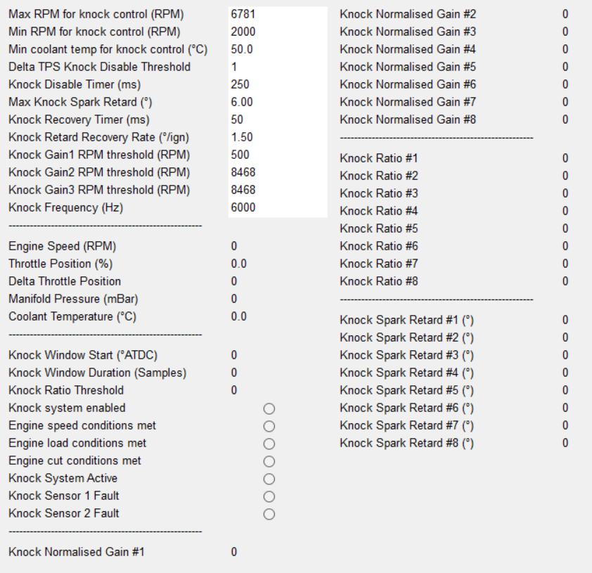
Image: the knock control settings as calibrated in the