Calibration & Control
Wideband lambda & closed-loop fuel control
Configure the wideband hardware, validate the CJ125 diagnostic and commission closed-loop fuel control.
1. Select and verify the sensor
In Sensor Setup, select the correct Lambda Sensor Type. The CJ125 diagnostic for each fitted sensor should show 0xFF when the sensor and controller are connected and operating correctly.
2. Select the control mode
Choose Single Wideband Control for one wideband sensor or Stereo Wideband Control for two. Applications using post-catalyst narrowband control should select the corresponding combined mode where provided.
3. Limits and correction
The maximum closed-loop correction limits how far the controller may alter fuelling. RPM and load limits determine where closed-loop operation is allowed; on a TPS-load calibration the load limit is shown as a TPS limit rather than MAP.
The Delta 900 function description uses 30% as a commissioning example, not a universal calibration value.
4. Sensor heating and start delay
Do not enable closed-loop control until the wideband sensor can be heated safely. Exhaust condensation can damage a fully heated ceramic sensor, so the heater/start strategy must account for dew point and the application’s exhaust layout.
5. PI terms and target lambda
Calibrate proportional and integral terms for fast response without oscillation or excessive overshoot. Keep the base fuel/VE calibration close to the desired lambda so the controller performs trimming rather than compensating for large base-map errors.
Wideband and closed-loop pages
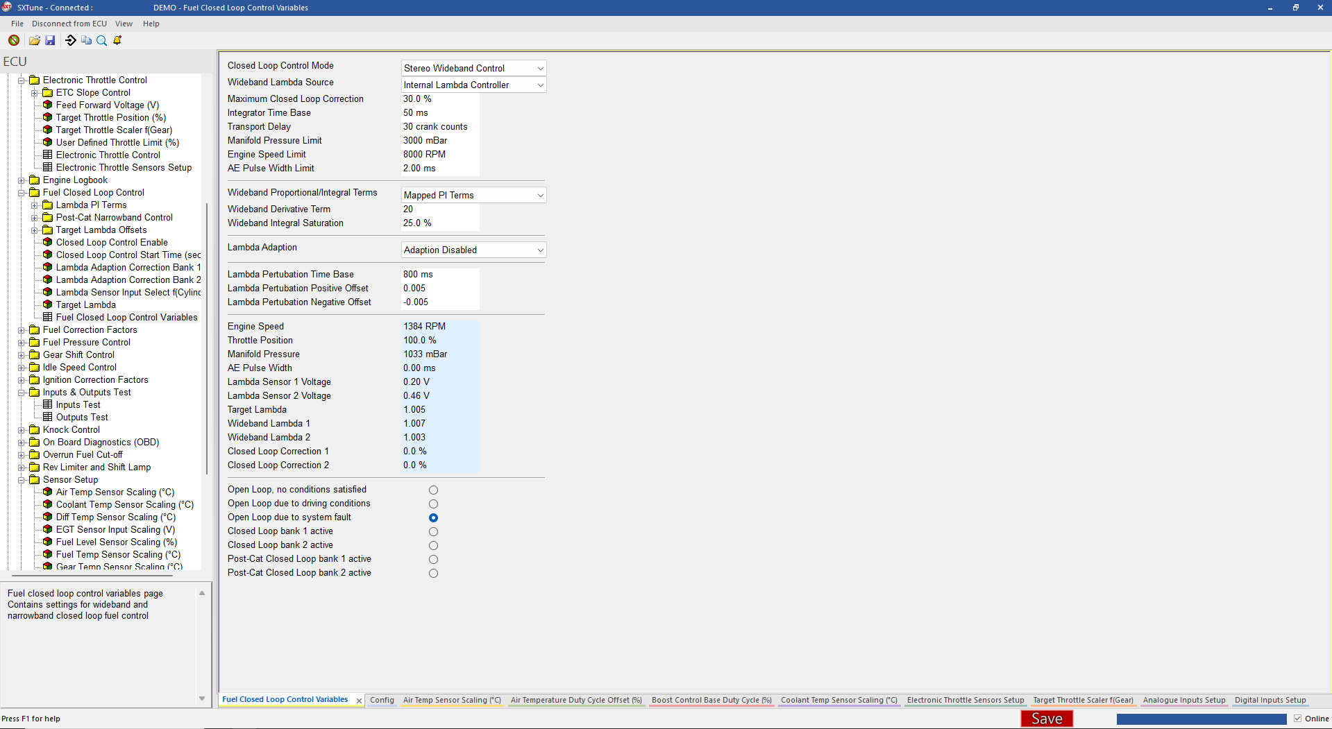
Closed-loop fuel control strategy
The first step is to Select the right Sensor in the calibration.
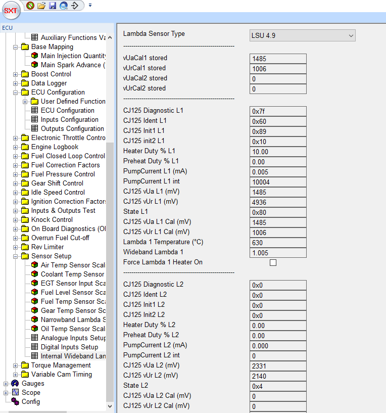
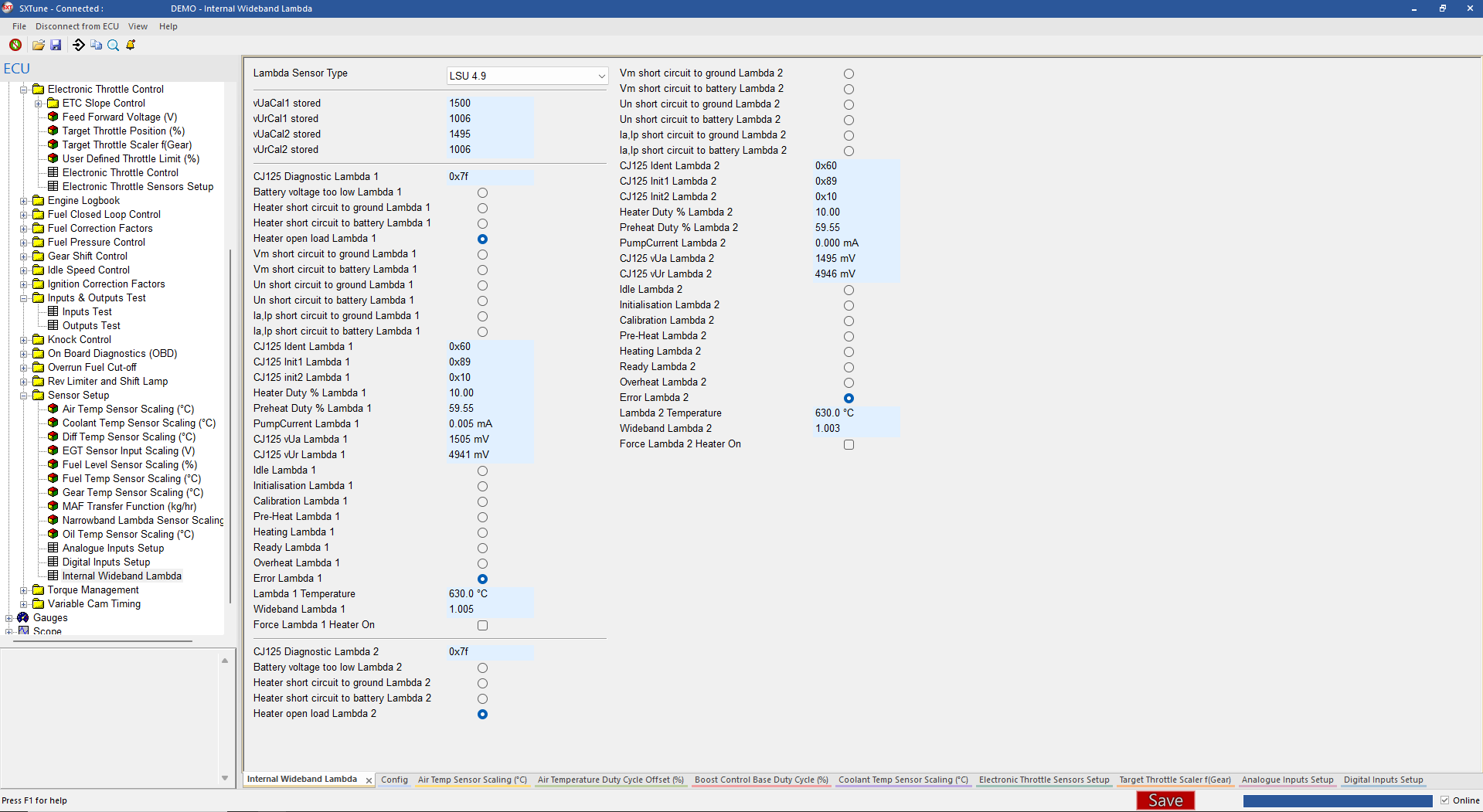
To setup the External wideband lambda controller, choose the correct sensor type in the Lambda Sensor type drop down. The C125 Diagnostic L1/L2 will show 0xff if the sensors are connected and working correctly.
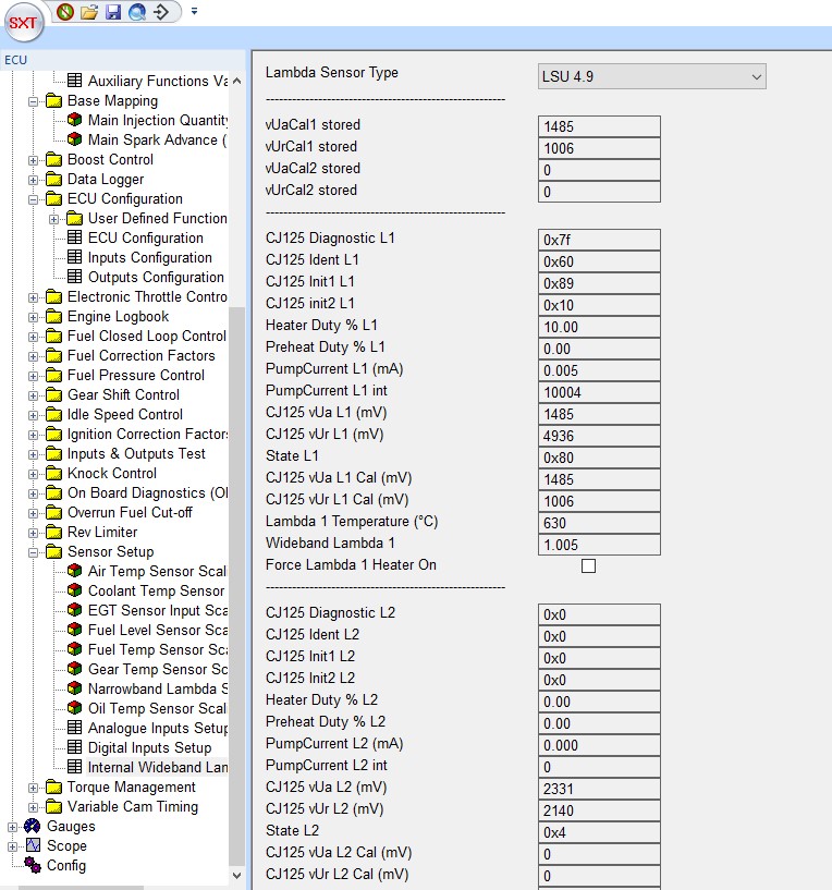
Image: CJ125 wide band lambda controller chip settings.
Closed Loop Settings
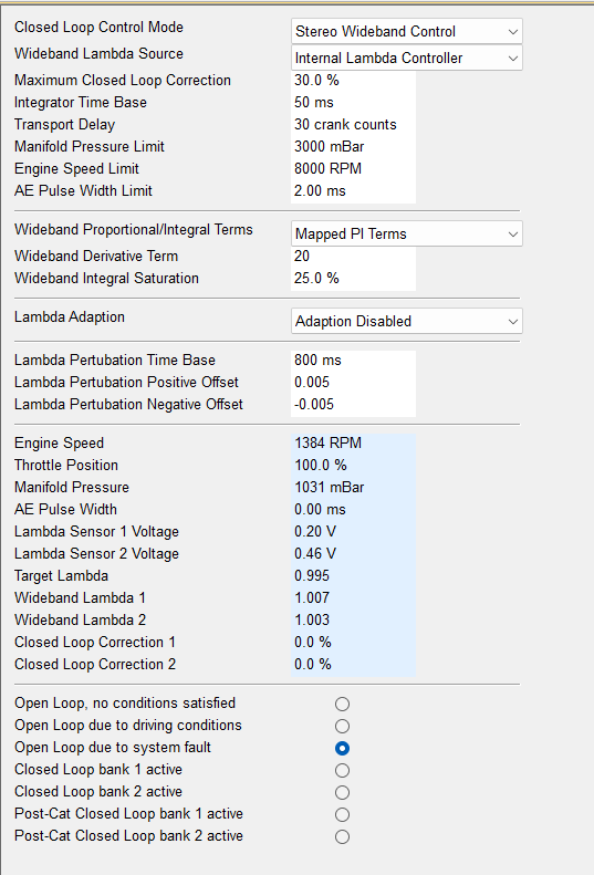
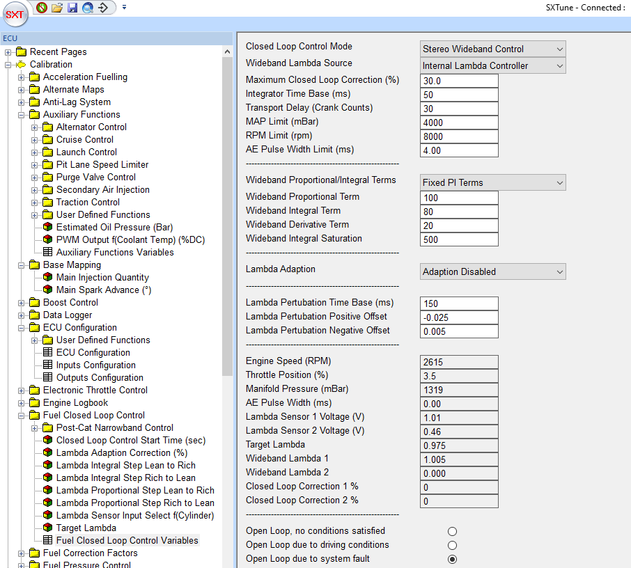
Choose Stereo Wideband Control for two wideband sensors, Single Wideband Control for one. For road cars with emission requirements it is necessary to also use the Post Cat Narrow Band control. The closed loop control settings should therefore be set as shown below:
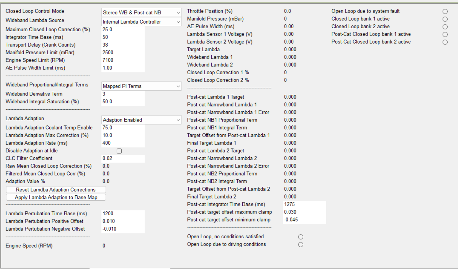
Image: The closed loop control settings
Make sure the sensor has been calibrated (see Lambda Sensor Calibration for details). Before populating a target lambda map, it is necessary to configure the variables which will determine how the map is used
1. In the Fuel Closed Loop Control group, select Fuel Closed Loop Control Variables and set closed Loop Control Mode to Wide Band Control + PC NB control. For a 2 Bank engine, choose the Stereo Wideband Control + PC NB.
2. The Maximum Closed Loop Correction value will set the maximum by which correction can alter the injection pulse width set in the Main Fuel Map (found in the Base Mapping group menu). For example, consider a global maximum pulse width variable set to 10ms and the value in the base fuel map for 2000RPM and load of 400mBar is 50. Before closed loop correction, the final pulse width would be 5ms. With a maximum correction factor set to 30% the maximum amount of fuel pulse width the closed loop correction could add or remove would be 1.5ms. It is recommended as a starting point to set Maximum Closed Loop Correction to 30%
3. Closed loop lambda control can be limited to operate up to a defined RPM and Load using the RPM Limit and Map Limit fields (Note: the load will show as TPS Limit (rather than Map limit) if your load input type variable has been set as Throttle Position in ECU Configuration field under the ECU Configuration group). For example: setting these as 4000RPM and 400mBar means that closed loop control will be turned off above either of these limits and the fueling will be determined by the Main Fuel map and other correction factor. When using a wideband sensor, the window can be opened up completely to enable closed loop control over the entire operation range.
4. The start time of the closed loop control needs to be calibrated over the different engine start temperatures. We want to go closed loop as early as possible to have the perfect emissions control however when activated too soon, there is a risk of damaging the wideband lambda sensors due to the amount of condensation water still present in the exhaust system of the car. When the lambda sensor is fully heated meaning that the ceramic of the sensor is at its target temperature of 780°C any hit of water droplets on the ceramic of the sensor can cause it to crack, leading to terminal damage. Therefore the electrical heating of the lambda sensors needs to be reduced over a PWM value until the so called dewpoint is reached.
5. The lambda heater is electrical and controlled by the ECU through a PWM towards the ground. As can be seen in the picture below, the duty cycle is depending on the phase of evaporation as well as on the feedback of the measured internal resistance of the internal heater of the lambda sensor.
A good control of the lambda sensor temperature is very important because the lambda to pump current characteristics of a Nernst cell is quite sensitive to temperature impact as the picture below shows:
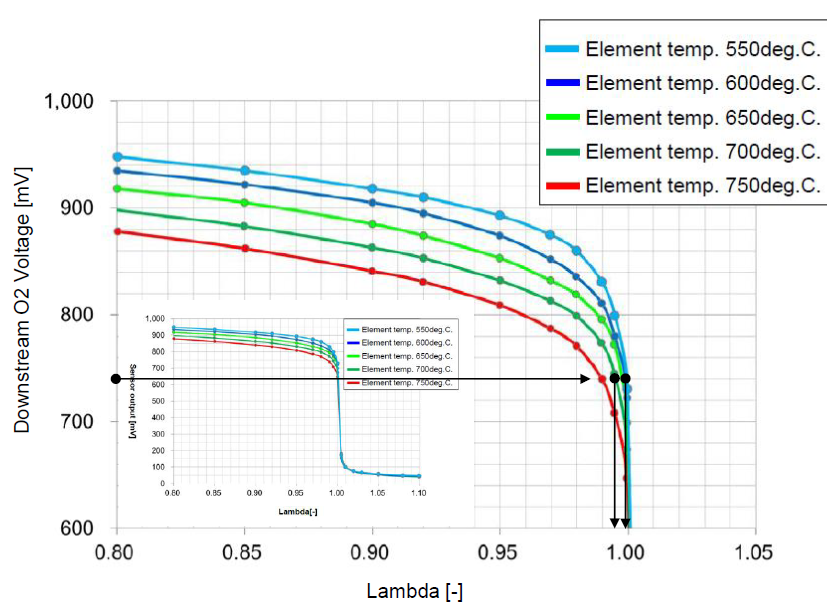
Image: lambda sensor characteristic over temperature
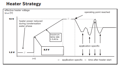
Image: lambda sensor heater strategy over the different phases
The dewpoint is the point where most of the water in the exhaust system is evaporated and thus the risk of water droplets moving down the exhaust system is reduced. Starting from this point, we can fully heat the sensors electronically after which it takes about 6s for them to get in their target temperature range. In the emission test temperature range meaning everything above -10°C, we accept a certain risk for heating the lambda sensors before the full dewpoint is reached in order to enable closed loop control as early as possible after start. This is possible because due to the active catalyst heating strategy, especially on engines with secondary air we create kind of a thermal reactor which is evaporating the water very very quickly.
Once the sensor has reached its operational temperature range, we activate a closed loop controller for the sensor temperature which is installed inside the CJ125 chip. Based on the measured internal resistance of the heater element of the lambda sensor, the controller will either increase or decrease the PWM for the heater control in order to stay on the target temperature as accurately as possible.
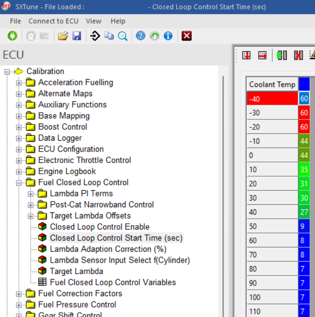
Image: closed loop start time calibration
Since on secondary air injection applications we do not want to drive closed loop control during the SAI, typically we start the closed loop just 1s after stopping the SAI pump.
5. The gain terms determine how quickly a difference in actual and target lambda is corrected and by how much the correction can overshoot the desired value. These gains are all speed and load depending and need to be calibrated in such a way that the control is as quickly as possible without creating undesired overshoots and oscillations. They can be calibrated unsymmetrically for the lean to rich and rich to lean directions, however it is important to make sure that the asymmetry is not too big as this will lead to poor control under dynamic situations.
Here is an example of calibrated maps.
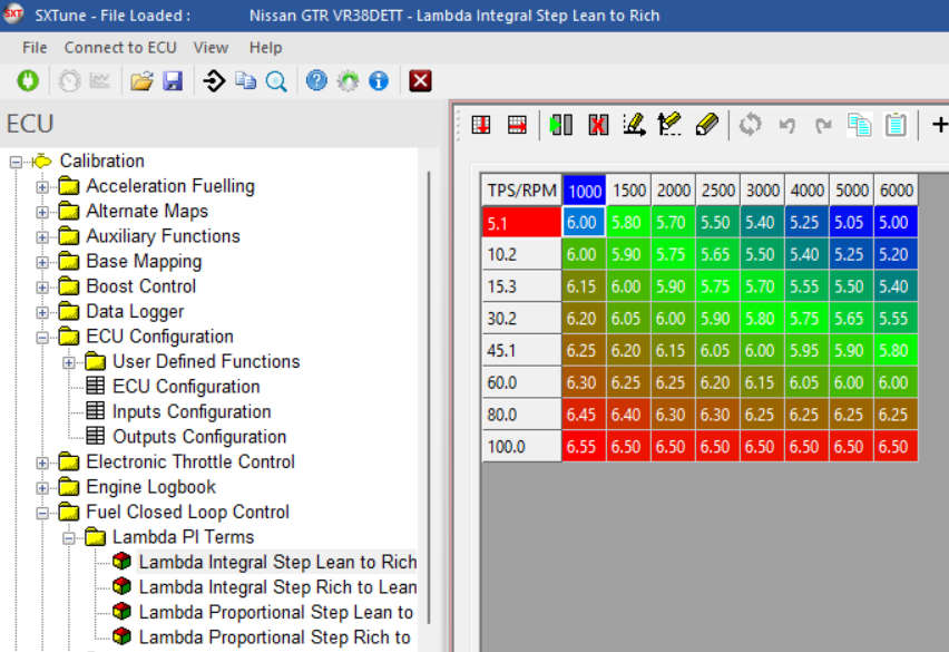
Image: a calibrated lean to rich integral gain map
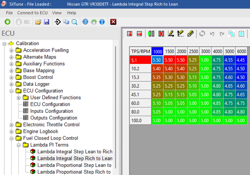
Image: The rich to lean integral gain map as calibrated on the
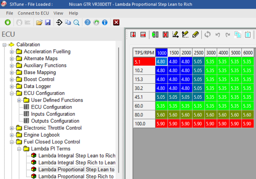
Image: The to rich proportional gain map as calibrated on the
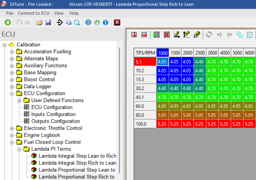
Image: The rich to lean to rich proportional gain map as calibrated on the
For the derivative D- gain it is recommended to not go over a value of 15, it can be set in the main closed loop fuel control overview map as showed in the picture below.
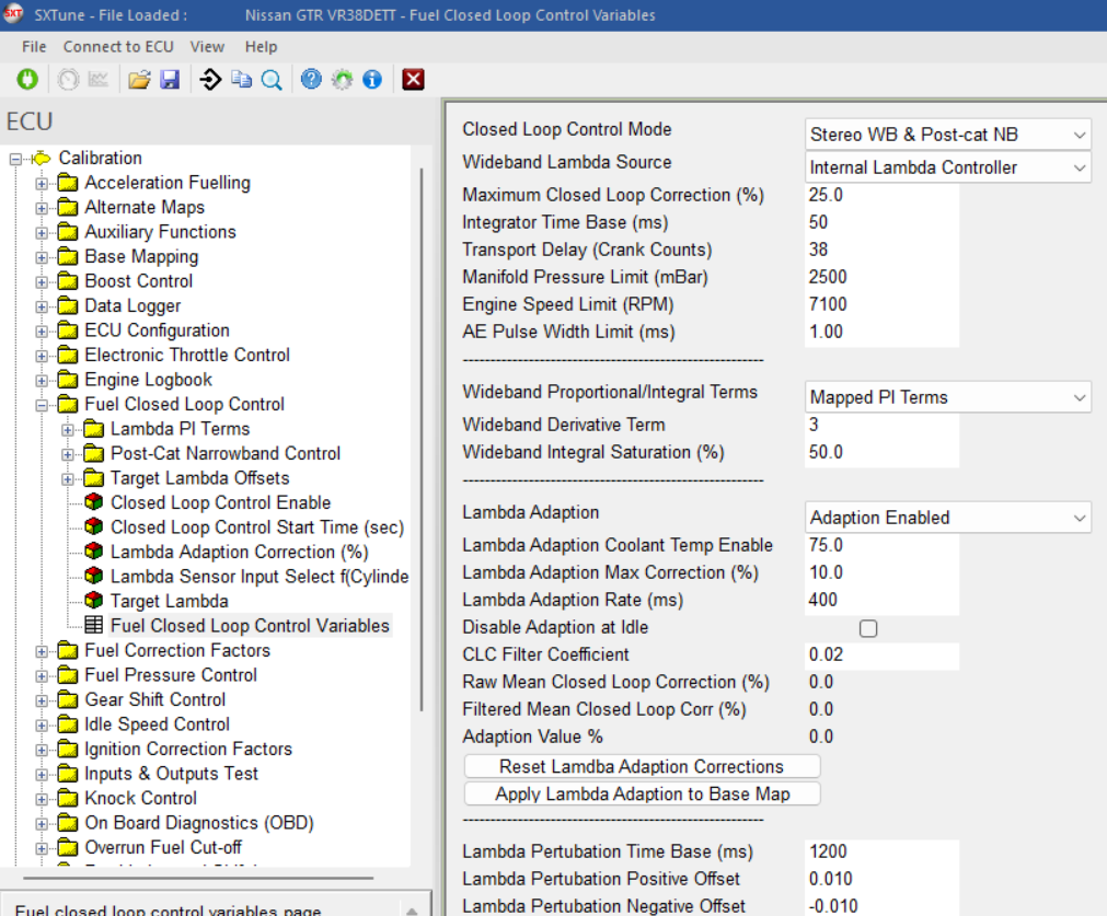
Image: the main overview table for closed loop fuel control as calibrated on the
Mapping Target Lambda
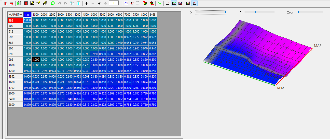
The target lambda values for various RPM and load conditions are set in the Wideband Target Lambda map. A typical Wideband Target Lambda map is shown below. Many tuners prefer to have lambda 1 at low loads and speeds. In contrast, when the engine is operating around the rpm where it makes most power then many prefer to run the engine at around .85 to .88 lambda in order protect the engine from excessive heat. When running turbo charged engines, many tuners tend to choose 0.8 lambda when at the RPM where the engine makes its maximum power. This value avoids excessive heating as well as making the engine less prone to knock. In all cases these are general rules of thumb preferred by different tuners and customers should carefully consider their own application’s requirements.
Editing Breakpoints
To set up the graph axis more breakpoints (rows or columns) can be added (up to a maximum of 8) using the edit icons. The windows provide for a maximum of 8 breakpoints on each axis. If less than 8 breakpoints are required on either axis, then the lowest breakpoint values can be repeated as shown in the MAP breakpoints edit window shown below. Notice that there are 5 unique values (breakpoints 1 to 4 have the same value) on the x axis (load) giving the 5 rows on the Wideband Target Lambda map. Return to the map view by pressing the pencil icon.
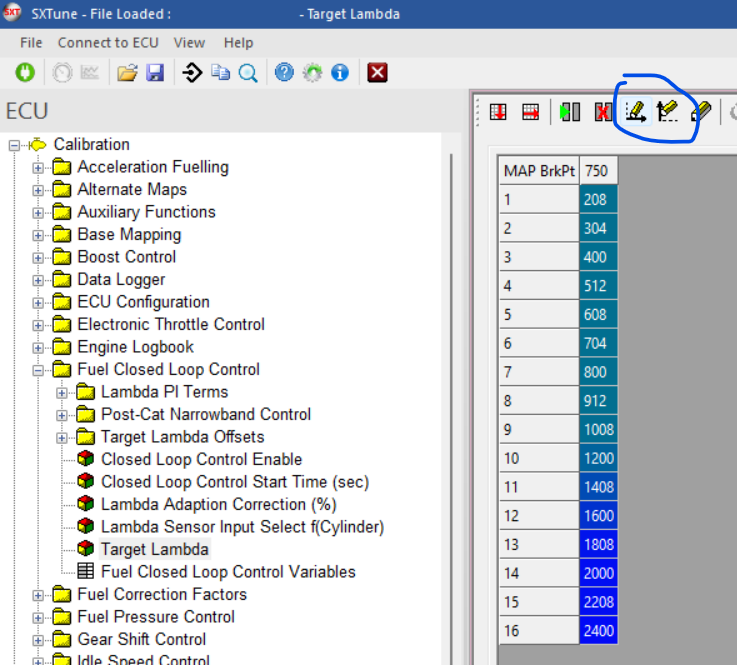
Image: editing the the target lambda map breakpoints
Improving Open Loop Lambda
As in other cases where closed loop control is used (e.g. turbo boost control), the accuracy of the base map (Main Fuel Map/ volumetric efficiency calibration) should be as close as possible to the desired lambda values for all RPM/Load combinations. For this reason, it is recommended to log lambda correction in real time and note the RPM/Load values where a lot of correction to the base fuel map is required in order achieve the values in the Wideband Target Lambda map. With Fuel Closed Loop turned off, the Main Fuel map values can then be gradually adjusted so that less (or ideally no) correction is required.
As with all calibration activities it is important to keep maps harmonic and smooth, big jumps in the basic maps will cause trouble for the closed loop controller to react to which will upset the system and lead to big inaccuracies during dynamic use.
After tuning the basic fueling maps, Closed loop control can then be turned back on and the smaller correction requirements should then be observed.
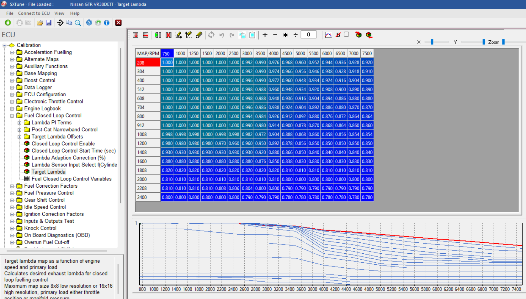
Image: the target lambda map as calibrated on the
The target lambda map is calibrated to lambda equally to 1, wherever possible for optimal fuel efficiency and emissions control. However at higher engine speeds and loads, this would lead to overheating the exhaust side engine components: exhaust valves, exhaust manifold, turbo and catalyst would go over their temperature limits (usually around 940°C for the manifold and turbo) and get catastrophic damage. Therefore the target lambda in those operating points needs to be set to richer values which cools down the exhaust system and therefore acts as a component protection.
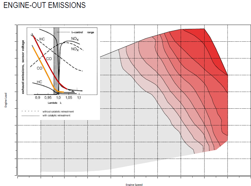
Image: the target lambda map
Fuel adaption strategy
When running the engine with wideband lambda control, you can use a slowterm fuel adaption strategy which learns the average filtered correction of the closed loop over a certain time period for each speed/ load point of the main fuel map. This strategy is designed to compensate for the small production tolerances over the different engines used in the series production of a vehicle type and thus make sure that all of them maintain the same fuelling control and thus also the same emission compliance. This is necessary to make sure that the open loop fuelling in the first seconds after start is always the same, also over the lifetime of a certain engine it will compensate for deposits and other effects which change the air charge characteristics or fuel injection parameters and thus would deteriorate the quality of the open loop fuelling if left uncorrected.
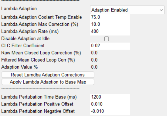
Image: the overview table for the closed loop control setting as calibrated on the .
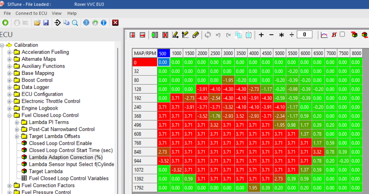
Image: the learned fuel adaption values
The lambda adaption max. correction decides the max. value of adaption, this can not be set too high due to the risk of creating unharmonically maps between the different speed/ load points. There is strategy in the background to smoothen the learned values by means of applying gravity centers of the learned value and extrapolating a certain percentage of the learned value to the surrounding operating points in the map.
The lambda adaption rate defines the time window over which a certain average value of closed loop controller deviation gets taken over by the fuel adaption. We recommend to go for high values here to get a more accurate result and keep dynamic behaviour out of the fuel adaption values.
The CLC filter coefficient defines how much the CLC input value is filtered by at PT1 filter. We recommend very small values here again to keep dynamic deviations out of it.
The lambda perturbation values decide the forced amplitude oscillation of the target lambda value for the upstream controller. This helps to keep the catalyst into its optimal 3way functionality window to convert both CO and HC on the rich side as Nox on the lean side at similar levels. If this perturbation amplitude is calibrated too high, it will cause driveability issues due to the lambda effect on the produced engine torque, therefore these values need to be limited to a max. of about 3% if it is needed for the emission conversion efficiency. Most systems will already work well with only 1% of amplitude however.
Post Cat Narrow Band lambda control
For full emission compliance, the use of a downstream catalyst lambda controller is essential.
In the SCS SW, we call this Post Cat Narrow Band lambda control. It has its own target lambda setpoint, which needs to be calibrated to achieve the optimal balance in catalyst conversion efficiency between CO/ HC and Nox.
Due to geometrical and other flow differences in the exhaust line, the found optimal values can be different between the different exhaust banks. This needs to be calibrated with emission analyzers downstream of the catalyst for each of engine the operation points.
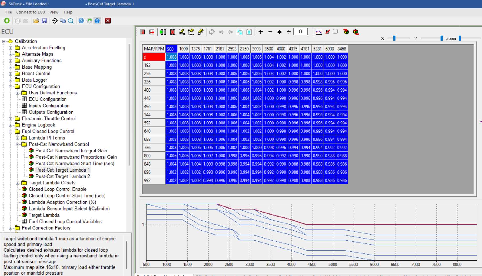
Image: the post cat target lambda map for bank nr. 1
The postcat control can only be activated after the downstream lambda sensor has reached its operating temperature. Also here the electrical heater can only be ramped up after the dew point at the position of this sensor is reached.
The output of the Post cat narrow band lambda controller is an offset onto the upstream lambda target value. If the downstream sensor sees a value leaner than its target, it will trim the upstream target rich and vice versa.
In this way with an optimal calibration it will keep the post cat lambda value onto its target value.
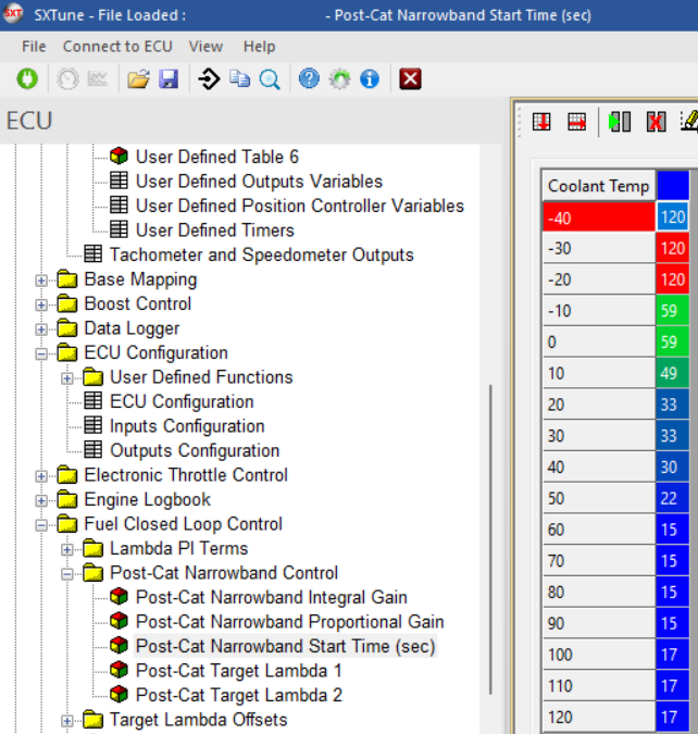
Image: the post cat narrowband activation time after engine start as calibrated in the , it enables the lambda controller shortly after the end of secondary air injection stops
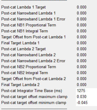
Image: the post cat narrowband control variables
Depending on difference between the measured PC NB lambda value and the target value, a PI controller without precontrol map will control an offset on the upstream lambda target value to help push the downstream target lambda to its target.
The following parameters need to be calibrated to achieve an optimal control with quick response but without big overshoots or oscillations.
P gain lean to rich and rich to lean
I gain lean to rich and rich to lean
Min and max clamp for the lambda target offset created by the postcat controller. These typically need an asymmetrical calibration to avoid lean overshoots as the Nox penalty for them would be quite big.
Here are some calibration examples:
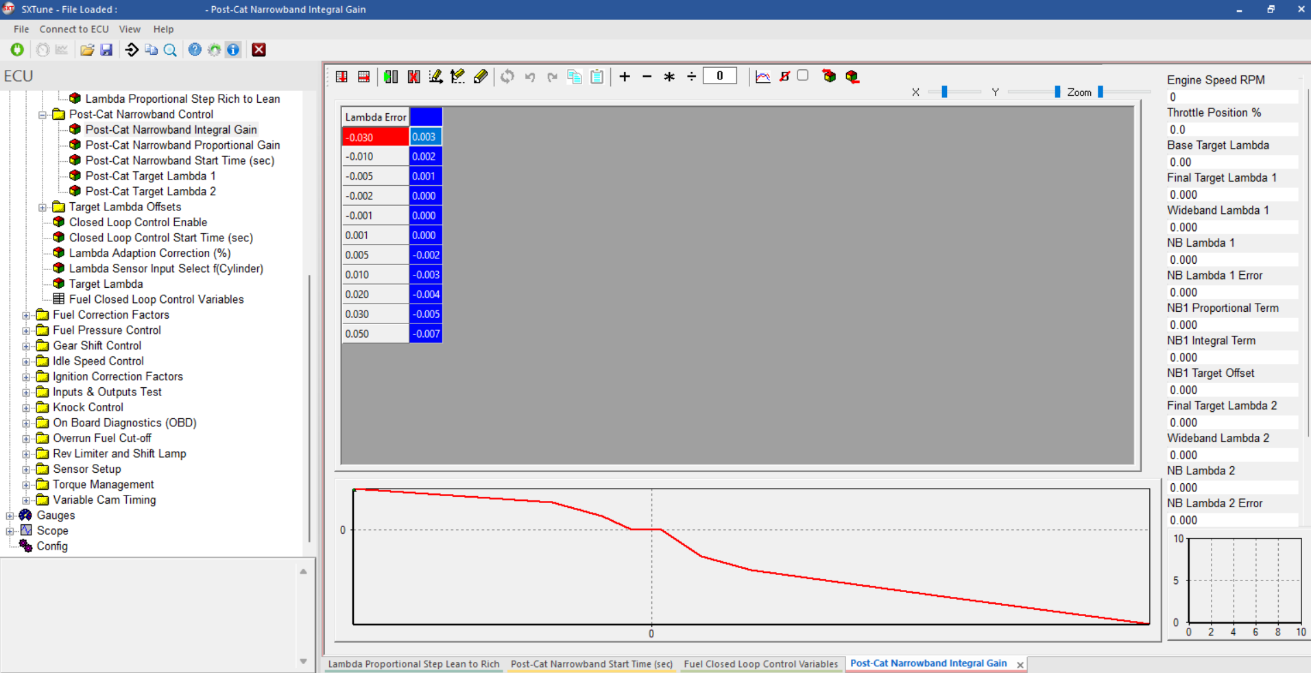
Image: the post cat integral gain table
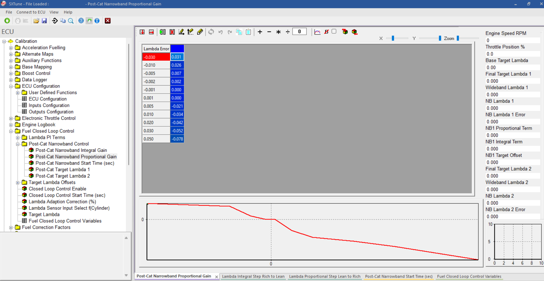
Image: the post cat proportional gain table
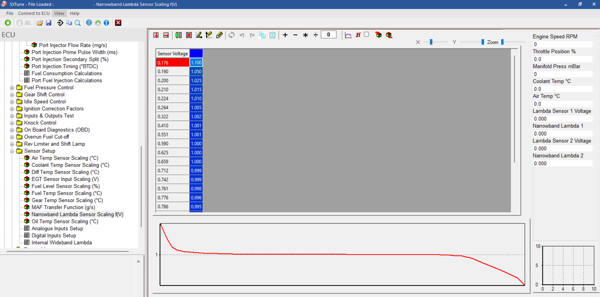
Image: the post cat narrowband sensor characteristic line
Closed-loop control settings