Add-on Modules
This page describes SCS Delta ECU CAN input/output streams in addition to configuration of some of the add-on modules compatible with Delta ECUs.
CAN Export Stream & User Defined CAN Inputs/Outputs
SCS Delta Log
Overview and Requirements
The Delta Log interface can be used to log up to 70 channels of data from the engine’s sensors. It is supplied with an 8Gb SD card, which is sufficient to log many days of continuous live data. The Delta log also acts as a USB-CAN interface for connecting the SXTune software for mapping the ECU.
The basic requirements are:
- Windows PC running Windows 7 or later.
- Delta Log Device
- A Delta ECU on a vehicle
- 12 volt permanent supply (Battery)
- Switched 12 volt supply (ignition switch)
- Latest copy of SXTune software installed
Configuring the Delta Log
Before using the logger, it will need to be configured in SXtune.
1. Install the latest version of SXTune. Make sure you are logged in as administrator and have the latest windows updates installed before installing SXTune. Connect the logger to a USB port on your computer (you do not need an ECU connected). Open SXTune and in the menu, on the left, open the Engine Calibration group and then choose the Data Logger sub menu, double clicking DeltaLog Configuration.
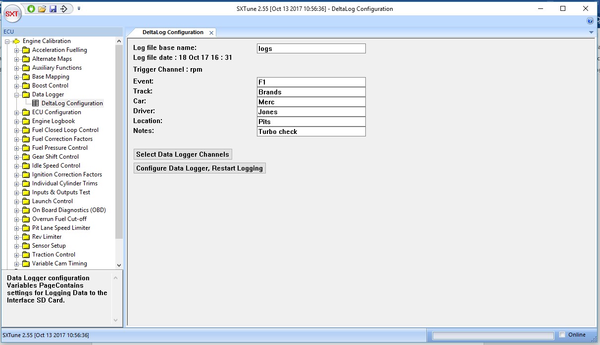
2. Choose a log file base name. This will be the name of the files on the SD card when they are viewed in Windows File Explorer. Each file will have a number appended to the name, with 0000 being the first file logged, 0001 being the second and so on. The Event, Track, etc information will be viewable in the DeltaLog software used to view the logged sensor information after an engine run.
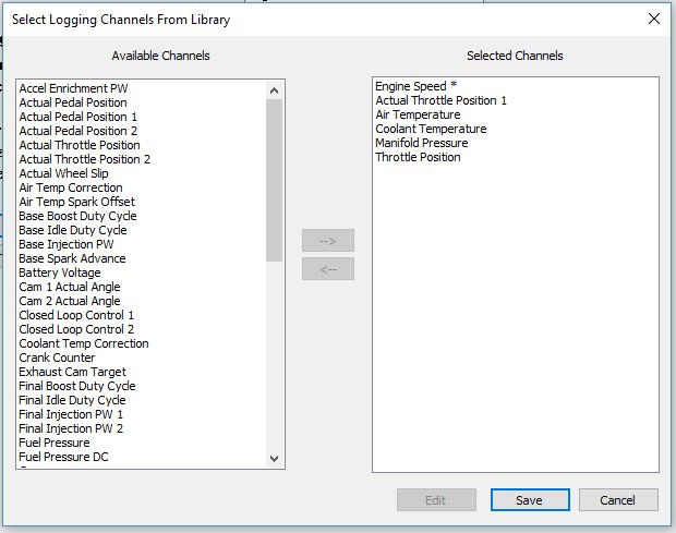
3. Click on Select Data Logger Channels and choose the signals to be logged by double clicking on them in the Available Channels window or using the arrows. Any channels in the Selected Channels windows can also be double clicked and they will move to the Available Channels. Once you have the channels you wish to log in the Selected Channels window the configuration can be loaded into the Delta Log device.
4. Click the Configure Data Logger, Restart Logging button and the configuration will be loaded into the Delta Log device.
5. The device can now be disconnected from the PC and installed into the vehicle by connecting it to the DB9 (or OBD) socket found on the wiring loom at the ECU end.
LEDs
The green power LED will be lit continuously to show the Delta Log has power. When the ignition is switched on the red LED will flash. When the engine begins to run the green LED will flash and the channels chosen during the configuration stage will be monitored and their signals written to the SD card until the engine stops running. This will produce one log (written to the SD card as a pair of files a .DTT and a .DTD having the same serial number e.g 0001). If the engine is run again a new log will be produced and will be given the next serial number in the sequence (e.g. 0002.)
PLEASE NOTE: When switching off the ignition, the power needs to be maintained to the logger in order for the logging file to be properly closed. If not, then you are likely to see an unclosed file on the SD card, indicated by having a 0 bytes file size, which cannot then be read. The ECU (which supplies power to the logger) usually has a permanent supply. If your application is configured such that the power to the ECU (pin 1 on the black plug) is cut when the ignition is turned off, you can still maintain power to the logger by having a laptop plugged into the logger's mini USB (SXTune must not be running though) which can be removed a couple of seconds after the ignition is switched off. Alternatively another power source can be plugged into the logger's mini USB port to maintain power (e.g. a USB charger). Another alternative is to run the thin purple wire going to your loom's DB9 connector (power wire to the logger pin 8) to a permanent 12v.
Viewing the Log
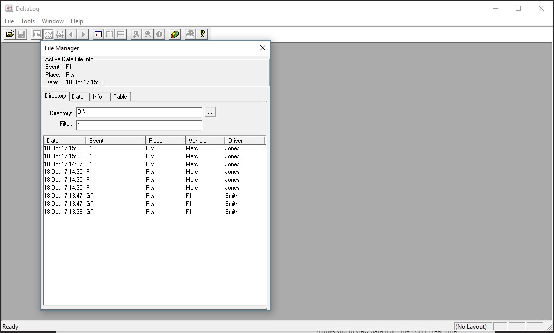
The ignition should be switched off and the SD card can be put into a Windows (7 or later) computer to view the log.
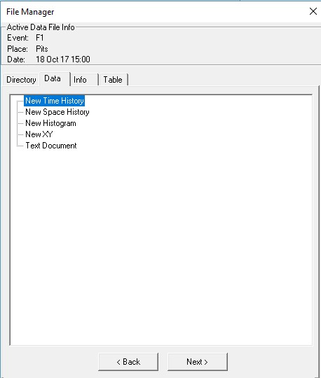
Start the DeltaLog software and choose File -> Open. In the Directory tab double click the log of interest.
The view will change to the Data tab where the lap can be chosen (usually 1) and the channels of interest highlighted (in blue).
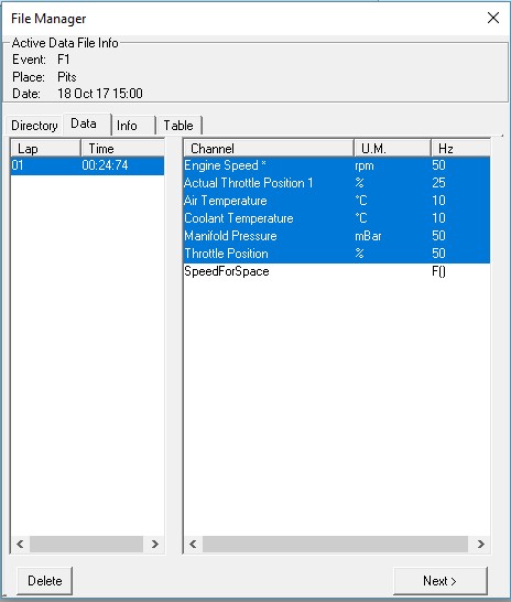
Clicking Next will bring up the graph type choices. Choose New Time History to see the signals as a function of time.
Analysing the Data
The vertical yellow cursor line can be moved around by placing the computer’s cursor anywhere in the graph and clicking.
By holding down the right-hand mouse button on the vertical yellow cursor it can be dragged to any point on the graph.
The exact values of the signals, where the vertical cursor bisects them, can be observed by looking at the Values Bar(F7 or Window -> Values Bar).
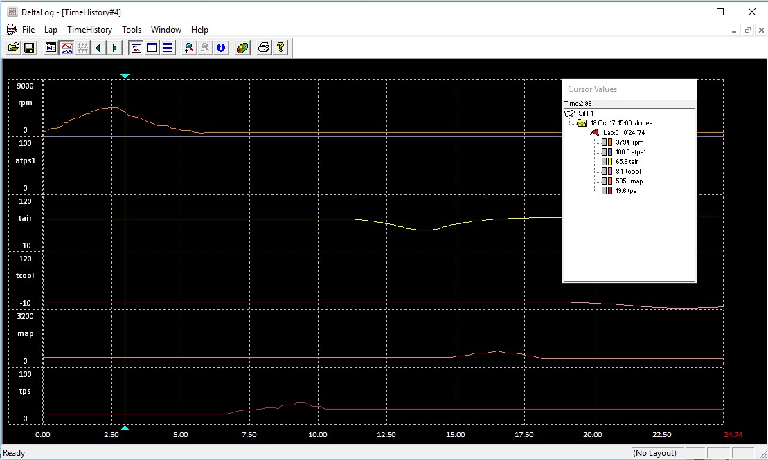
Right clicking on a signal, within the Cursor Values window, will allow you to change the colour of its trace in the graph.
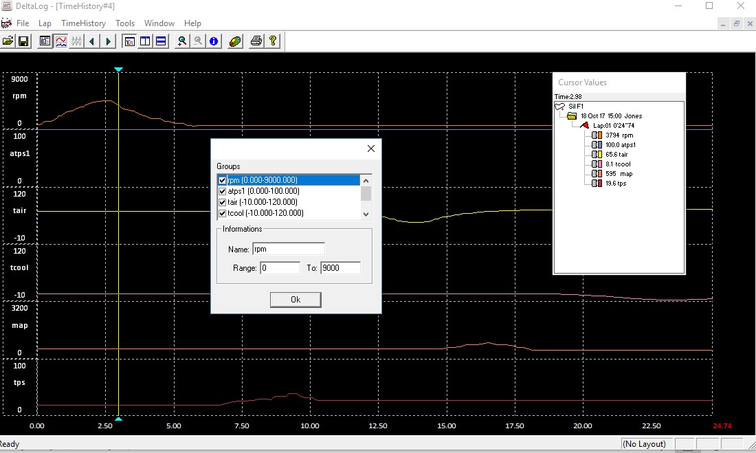
A section of the graph can be zoomed in time by clicking the magnifier icon on the toolbar and clicking the first point, keeping the mouse button down and moving it to the left until the end of the section you wish to zoom and releasing.
Choosing TimeHistory -> Configure the vertical axis can be adjusted for each signal independently in order to show the magnitude of each signal (as a function of time) in more detail.
Aim Dash
Configuring Dash
Aim's Race Studio 3 should be used to set up to work with the Delta ECU. This can be done in the ECU Stream section of the configuration page in the Race Studio 3 software, by choosing your ECU from the SCS options.
Configuring ECU
The AIM dash can be set up in the ECU Configuration page of SXTune:
For a Delta 400 ECU set the CAN Bus Speed to 1 Mbit/s and OEM CAN1 Output Configuration to Not Used
For a Delta GDI, SDI and 800 ECUs set the CAN Bus 2 Speed to 1 Mbit/s and OEM CAN2 Output Configuration to SCS Dash Comms
CANFormance TCU
Suitable for Delta 700, 880, 900 and GDI6 ECUs with firmware dated 01.06.2023 or newer
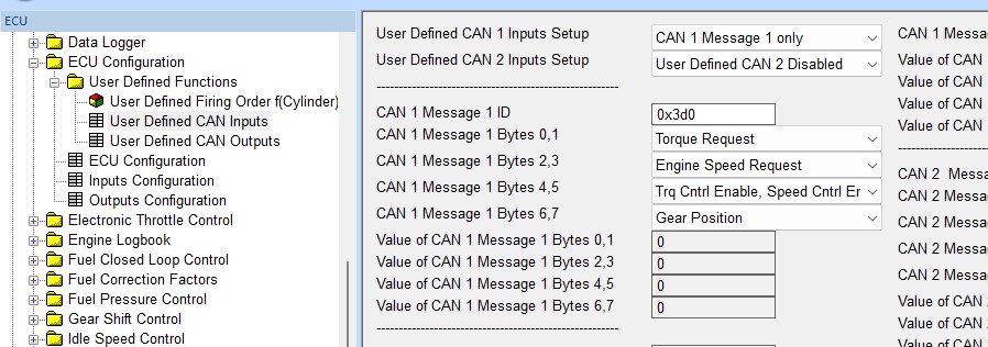
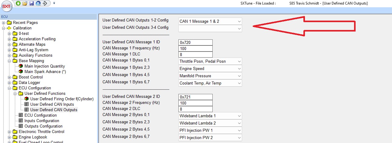
CAN Settings
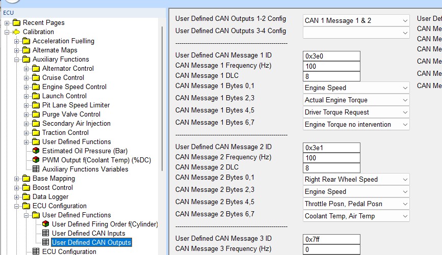
User defined CAN Inputs settings as below. Note that CAN 1 is selected, change to CAN 2 if required depending on which ECU CAN bus the CANTCU GCU is connected to.
User defined CAN output settings as below. Note that CAN 1 is selected, change to CAN 2 if required depending on which ECU CAN bus the CANTCU GCU is connected to.
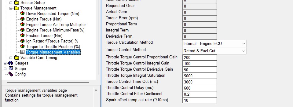
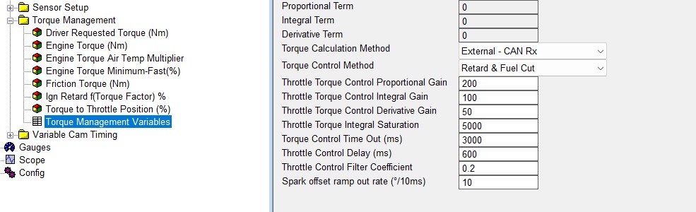
Torque Manager Settings
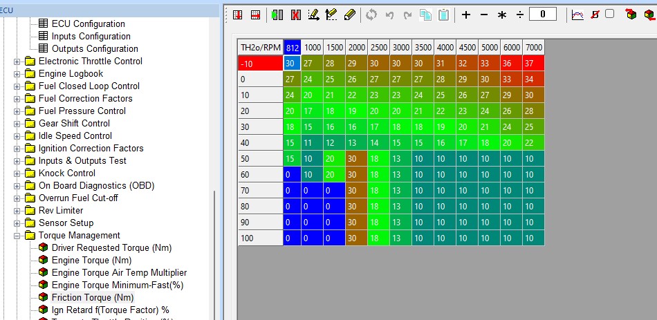
Set Torque Manager variables as below:
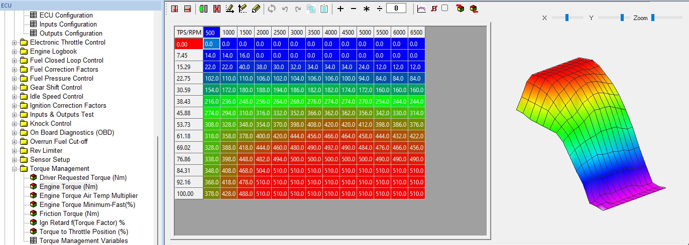
Example Engine Torque map – this should be calibrated on a dyno or rolling road, it can be estimated from a full load power curve
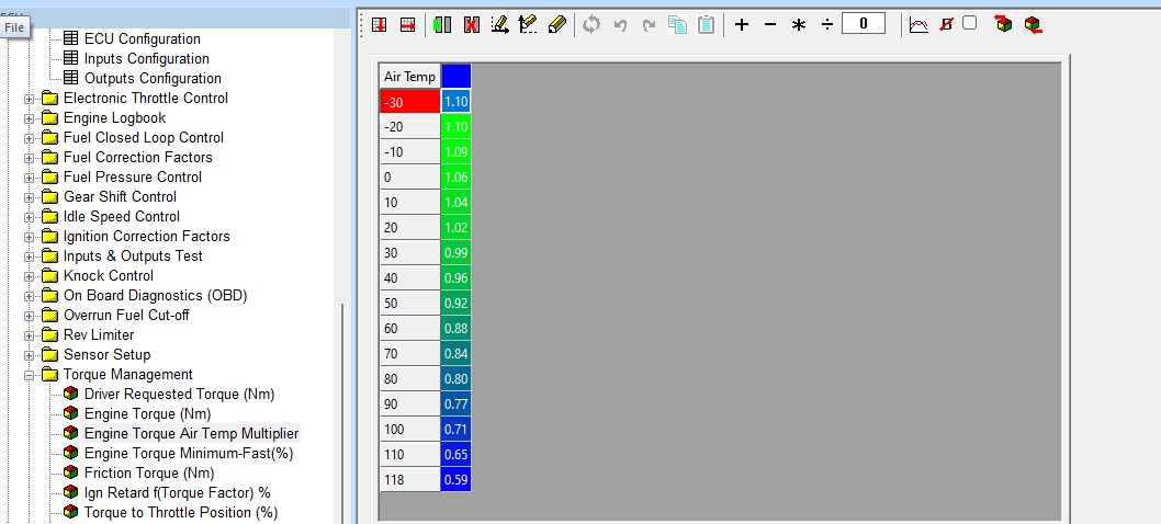
Engine Torque Air Temp Multiplier
Friction Torque example map
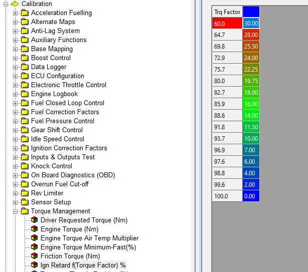
Ignition Retard f(Torque Factor) %

Engine Torque Minimum-Fast(%)
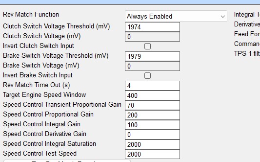
Rev Matching Settings
Downshift Rev Matching variables as below:

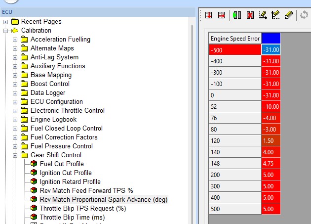
Rev Match Proportional Spark Advance example map:
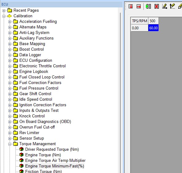
Rev Match Feed Forward TPS % example map:

HTG TCU
Suitable for Delta 700, 880, 900 and GDI6 ECUs with firmware dated 01.06.2023 or newer
HTG CAN Settings
User defined CAN Inputs settings as below. Note that CAN 1 is selected, change to CAN 2 if required depending on which ECU CAN bus the HTG GCU is connected to.
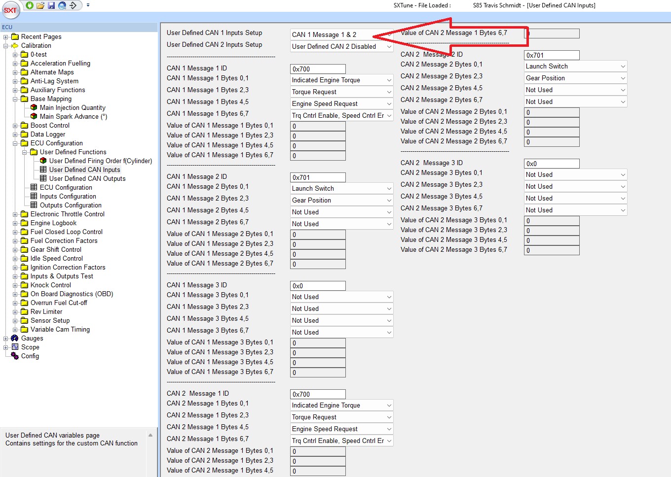
User defined CAN output settings as below. Note that CAN 1 is selected, change to CAN 2 if required depending on which ECU CAN bus the HTG GCU is connected to.
HTG Torque Manager Settings
Torque Manager variables as below:
Ignition Retard f(Torque Factor) %
Engine Torque Minimum-Fast(%)

HTG Rev Matching Settings
Downshift Rev Matching variables as below:
Rev Match Proportional Spark Advance example map:

Rev Match Feed Forward TPS % example map:
Configuration for Speedo Output
Setup Input Signal & Wheel Circumference
1. Wire a 3-wire hall sensor to a spare Hall Effect Input (which can be configured as a Wheel Speed Input).
2. Select the wheel speed option from the dropdown for that pin in SXTune – ECU Configuration – Inputs Configuration.
3. Go to Sensor Setup – Digital Inputs Setup in SXTune.
4. In the Wheel Speed Input dropdown, select Direct Input type. Enter number of pules per one wheel rev and wheel circumference.
5. Observe the Wheel Speed (km/h) signal as you drive the vehicle and observe your speed on a GPS unit or phone app.
6. Adjust wheel circumference until speed in SXTune is matching, or more usually a few Km/h, over, the speed observed on the GPS.
7. Save changes.
This speed is available on the CAN output stream for CAN dashes.
A traditional speedo clock will require setting of the Speedo Output Frequency @ 300kmh in the SXTune page: Auxiliary Functions – Auxiliary Functions Variables.
Adjust this figure until your speedo matches the speed shown in SXTune as the car is driven.
